This article provides an in-depth analysis of the role of MLCC in EV power modules, including parameter selection, derating design, and material selection, providing a valuable reference for engineers and technicians.
I. Role of DC-DC Modules in EV Power Architecture
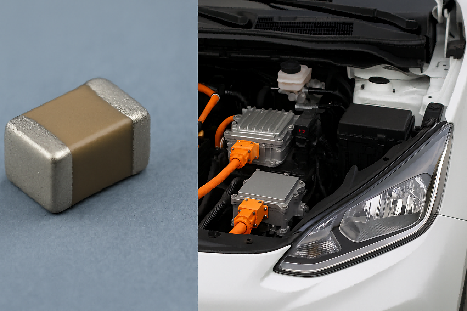
In electric vehicles (EVs), the power system must convert the high-voltage battery supply (400V or 800V) into suitable DC voltages for various low-voltage subsystems such as 12V, 5V, and 3.3V lines. The DC-DC buck converter plays a central role in achieving this step-down conversion efficiently and reliably.
Operating typically at tens to hundreds of kilohertz, these modules generate high-frequency switching noise, ripple voltages, and electromagnetic interference (EMI), which places stringent demands on passive filter components.
II. Why Are MLCCs the Preferred Capacitors?
MLCCs are unmatched in DC-DC modules because of their symmetric internal structure, ultra-low equivalent series resistance (ESR), minimal parasitic inductance, and excellent high-frequency response. These attributes make them ideal for filtering, bypassing, and decoupling tasks.
Compared to electrolytic or tantalum capacitors, MLCCs offer longer service life and lower temperature drift—key advantages in harsh EV environments that demand high reliability under thermal and mechanical stress.
III. Application Case: MLCCs in Buck Converter Topologies
Let’s take a typical buck converter topology to analyze how MLCCs are strategically deployed:
Input Filtering
MLCCs placed between the high-voltage input and the switching transistor suppress voltage spikes from high-speed switching and help contain EMI.
Output Decoupling
Parallel MLCCs (e.g., three 10μF X7R capacitors) at the output stage absorb ripple and provide a clean, stable DC output to the load.
Bypass at Controller VCC Pin
A 1μF–2.2μF MLCC with C0G dielectric near the VCC pin ensures noise-free power for the control IC, preventing erratic switching behavior.
IV. Packaging and Dielectric Considerations
The effectiveness of MLCCs depends not only on capacitance and rated voltage but also on dielectric materials and package sizes:
|
Type |
Recommended Use |
Features |
|
C0G |
High-frequency bypass and timing |
Excellent stability, low drift |
|
X7R |
Output filtering and input stabilization |
High capacitance, good value |
|
1206 |
Output near load |
Larger current capacity |
|
0805 |
General decoupling |
Balanced size and performance |
V. De-Rating Guidelines for MLCCs in EV Power Design
For EV applications, it’s vital to apply proper de-rating rules to MLCCs. Due to voltage spikes and temperature fluctuations, it’s standard practice to design MLCCs to operate at 50–70% of their rated voltage.
Moreover, to enhance mechanical stability and tolerance, avoid stacking large packages; instead, use multiple medium-sized capacitors in parallel.
VI. Future Trends: High CV and Automotive-Grade MLCCs
MLCC technology is evolving towards higher capacitance (High CV), smaller footprints (01005/0201), and wider temperature ranges (-55°C to +150°C) to meet automotive-grade standards like AEC-Q200.
Some leading manufacturers are also developing flexible termination MLCCs to enhance mechanical resilience post-soldering, reducing cracking risks under thermal cycling.
MLCC | Electric Vehicle Capacitors | DC-DC Filtering | High-Frequency Bypass