Több fordított極s polaritás-védelmi kör ismertetése autók elektromos elejénél, beleértve a Schottky-diódákat, a P-/N-csatorna MOSFET-eket és vezérlőalapú megoldásokat. Kiválóan alkalmas akkumulátorkezelőrendszerre (BMS), autó-elektronikai ECU-kre és EV teljesítménymodulokra alacsony hatalomveszteséggel és gyors válaszidővel mind dinamikus, mind statikus fordított polaritás-védelem igényei miatt.
—— Fordított polaritás elleni védelem technológiája magyarázata
1. Mi az a fordított polaritás elleni védelem?
A fordított極ségvédelem (RPP) arra szolgál, hogy megakadályozza a rendszerek károsodását akkor, ha egy akkumulátort fordítva csatlakoztatnak. Gyakran található autók elektronikai áramkörében, Akkumulátorkezelő Rendszerekben (BMS), valamint különféle alacsony feszültségű DC bemeneti modulokban.
Három alapvető típusú fordított polaritás védelmi kör létezik:
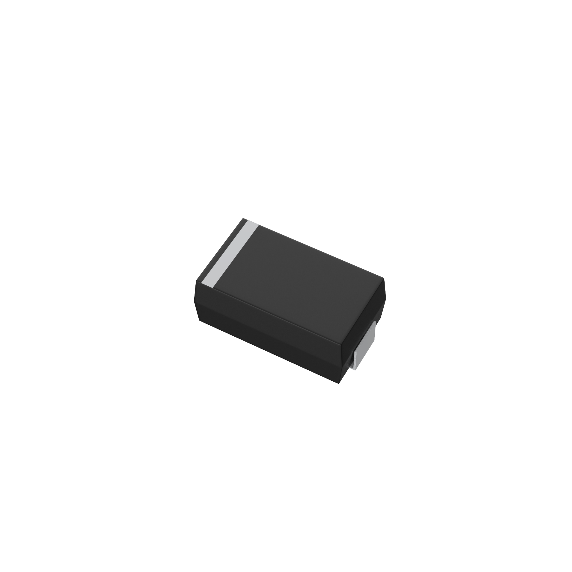
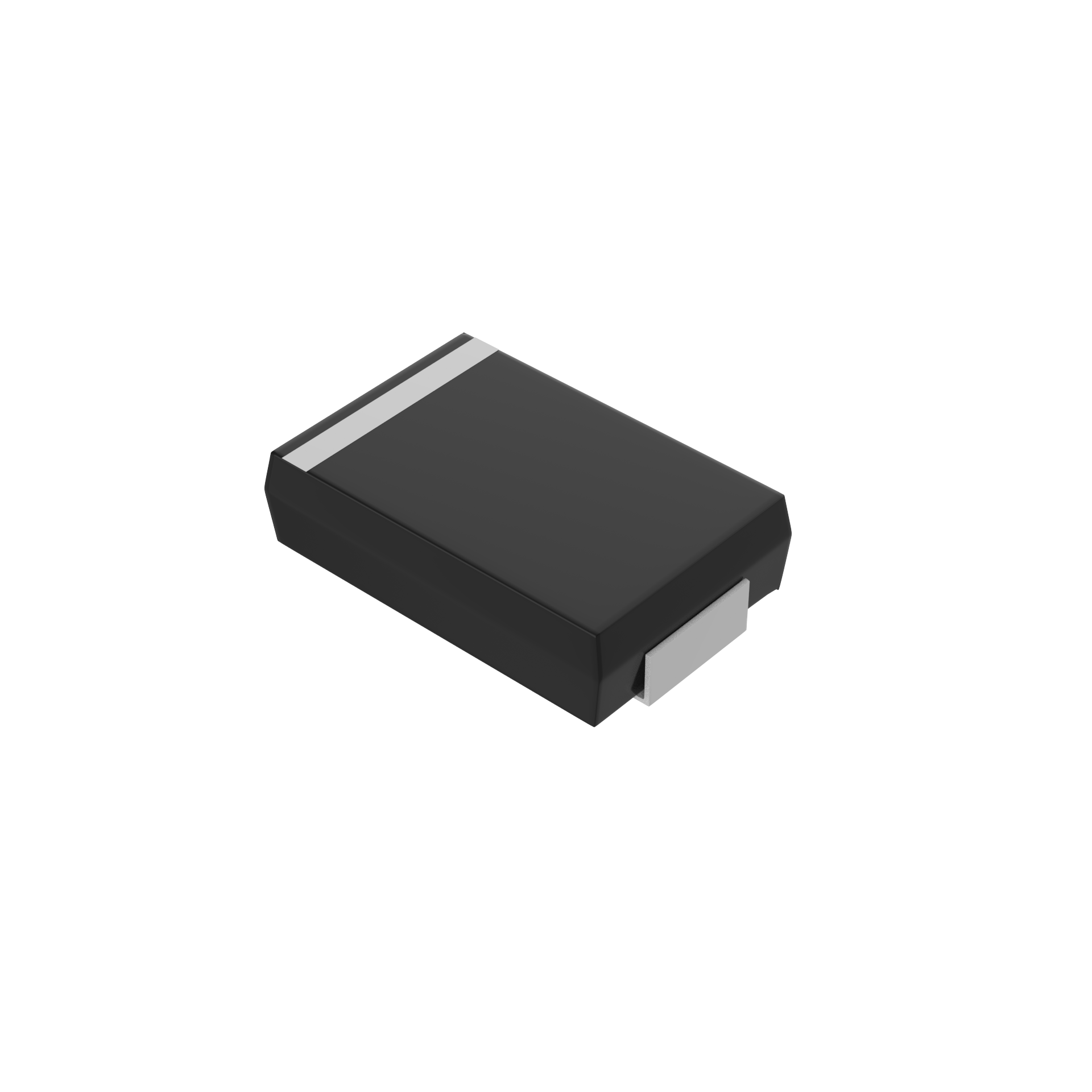
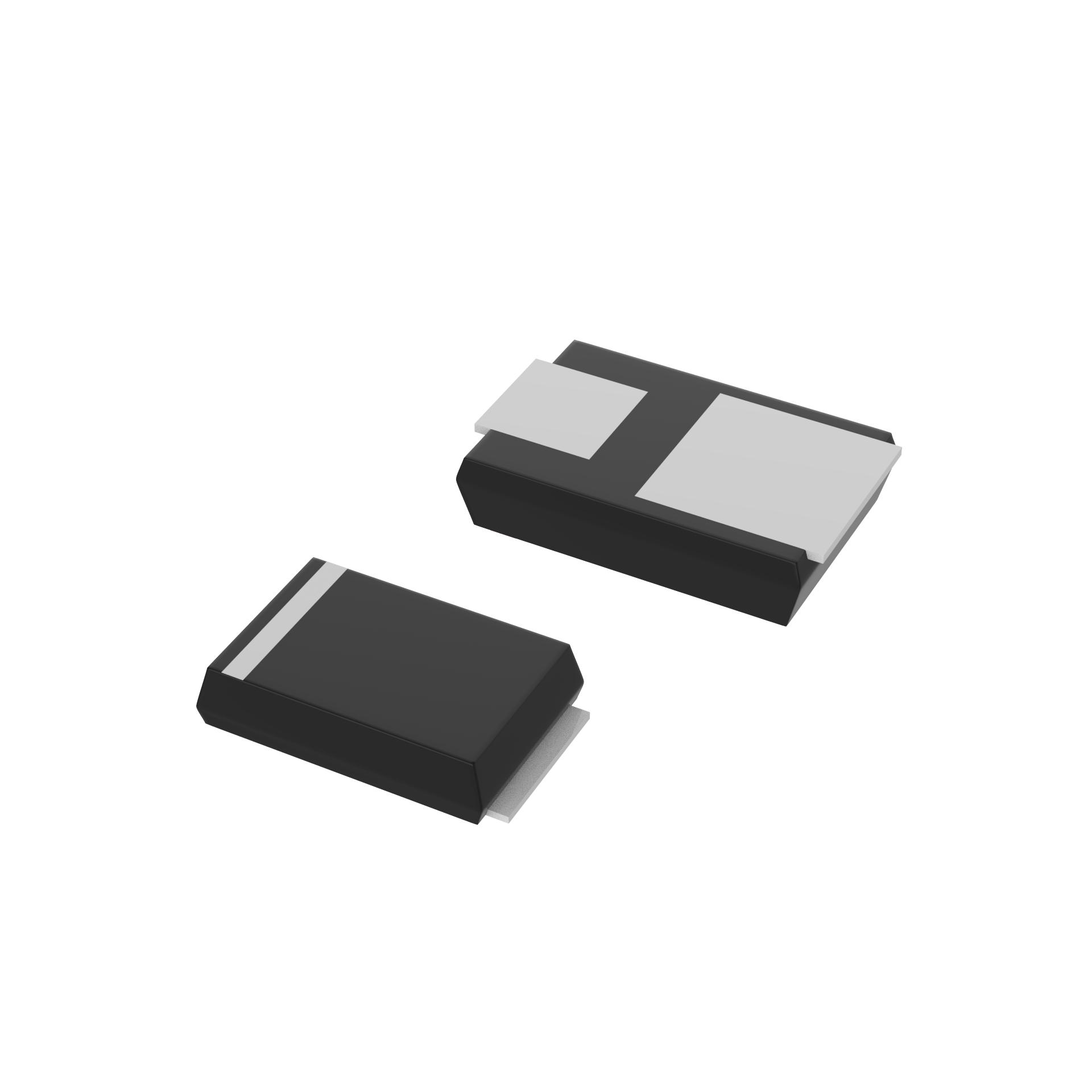
- Soros szabványos/Schottky dióda
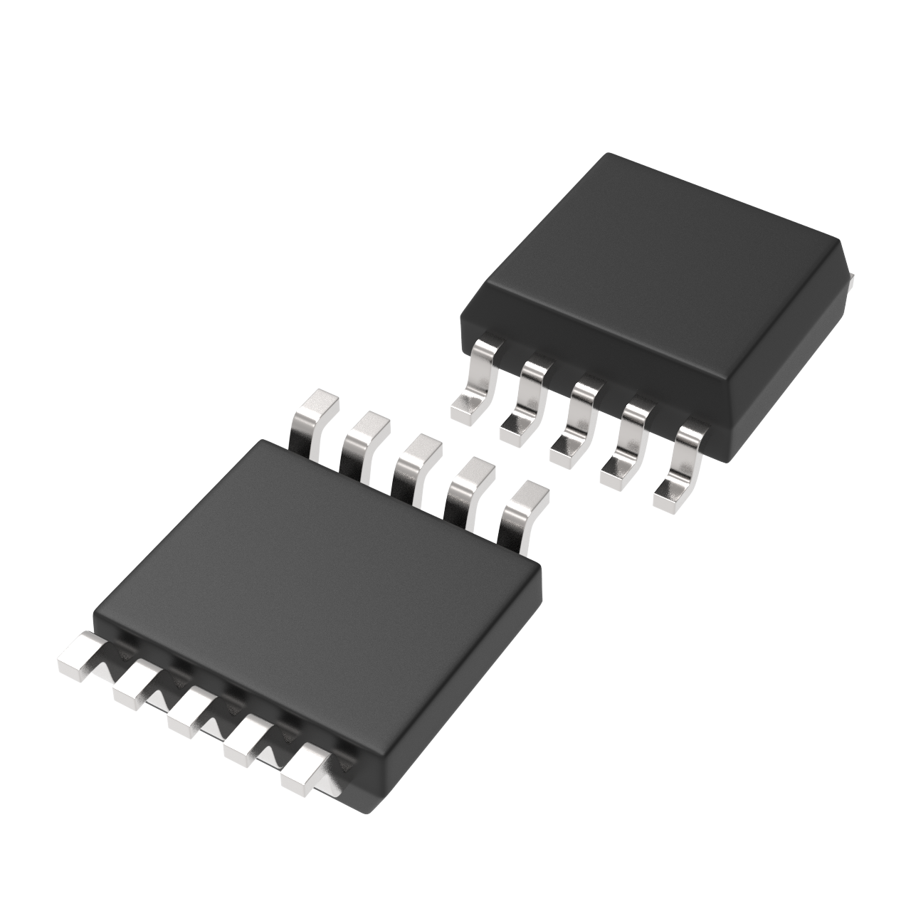
- Felső oldali P-csatorna MOSFET
- Felső oldali N-csatorna MOSFET
2. Főáramú Fordított Polárás Védelem Megoldások
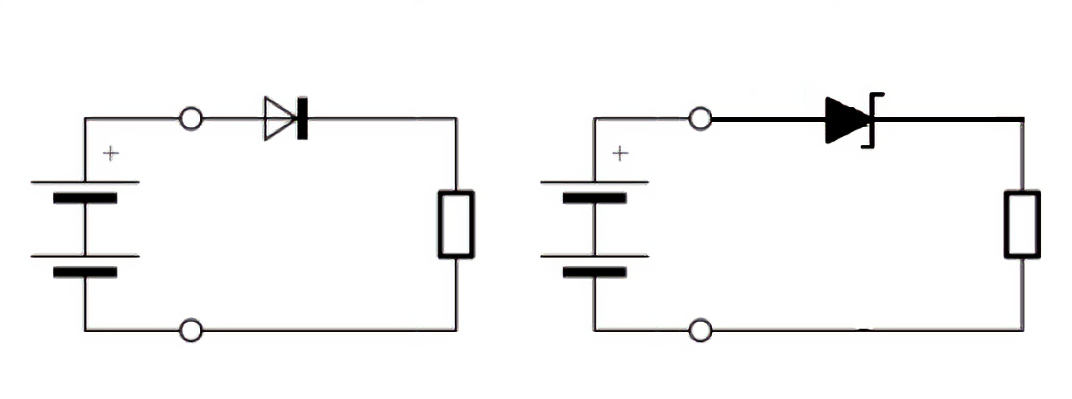
2.1 Dioda Soros Metódus
Alap-elv: Egy szabványos vagy Schottky dióda helyezésre kerül a pozitív áramút sorába, és csak akkor vezet, ha a polárás helyes.
Technikai Összehasonlítás:
|
Típus |
Előrébbi Feszültségcsökkenés (V) |
Előnyök |
Hátrányok |
|
Szabványos dióda |
0.7 ~ 1.0 |
Egyszerű, alacsony költség |
Magas feszültségcsökkenés, magas teljesítményveszteség |
|
Schottky-dióda |
0.2 ~ 0.5 |
Alacsony feszültségcsökkenés, magas hatékonyság |
Nagyobb áramfolyás-hullámtétel |
Alkalmazás: Alkalmi vagy költségsz敏g-sensitive alkalmazások.
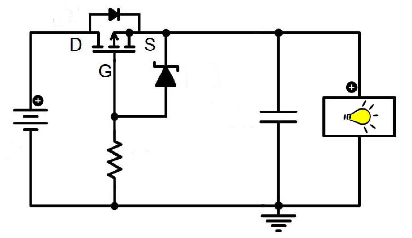
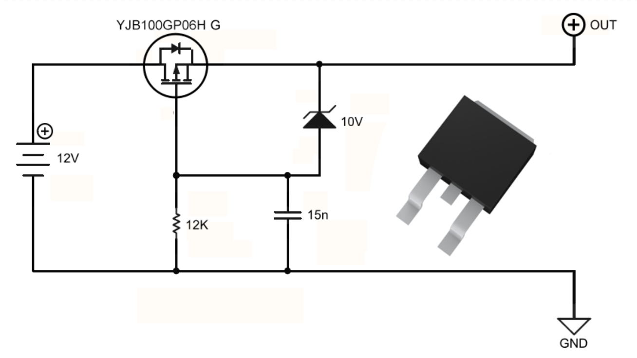
2.2 P-szintű MOSFET megoldás (Ajánlott)
Körstruktúra: Egy P-csatornás növekmény MOSFET helyezkedik el sorosan a pozitív áramkörrel, gyakran egy Zener-diodával a kapcsoló védelmezésére.
Működési elv:
- Helyesen csatlakoztatva a MOSFET testdiodája vezet, és a Source terminál kap batteriagyárt.
- A Gate 0V-ban van, ami az Vgs-t negatívvá teszi, és bekapcsolja a MOSFET-et.
- A Zener-dioda korlátozza az Vgs-t a rögzített feszültségre.
Fordított csatlakozáskor: A testdioda fordított irányban van, a MOSFET ki van kapcsolva, a kör törött, és a rendszer védett.
Előnyök: Nagyon alacsony bekapcsolási ellenállás, sokkal alacsonyabb hatalomveszteség, mint a diódák esetében. Nem szükséges külső vezérlő.
Alkalmazás: Gyakran használják az autóelektronikában, az ECU-kben és a BMS elejei front end-ekben.
2.3 N-szintű MOSFET megoldás (magas teljesítmény)
Jellemzők:
- Alacsonyabb Rds(on), mint a P-csatornánál, alkalmas magas áramrendszerhez.
- A kapukhoz töltőpumpa vagy boost vezérlő szükséges, hogy a Vgs a forrás felett legyen.
Fordított kapcsolásban: A test diódja fordított irányba van polarizálva, a kapu vezérlése letiltva, és a MOSFET ki marad.
Alkalmazás: Kiválóan alkalmas magas hatékonyságú rendszerekhez, például az haladó EV-vezérlőkhöz.
2.4 Vezérlőalapú Megoldások: RPP vs. Tökéletes Dióda Vezérlők
|
Vezérlő típus |
Jellemzők |
Fordított áram blokkolása |
|
RPP Vezérlő |
N-kanálú MOSFET-tel működik, csupán fordított極性 védelmet nyújt |
No |
|
Ideális Dioda Vezérlő |
Fordított極性 + fordított áram zárolási védelmet nyújt |
Igen |
3. Dinamikus vs Statikus Fordított極性
Statikus Fordított極性: Hosszútávú fordított kapcsolódás, stabil védelem szükséges.
Dinamikus Polárítás Fordítása: Ideiglenes fordított kapcsolódás, például pillanatnyi rossz behelyezés esetén gyors válasz szükséges.
4. Gépi Relé Védelem (További)
Előnyök:
- Magas csomagáramot bír el minimális feszültségesés nélkül.
- Teljes körű áramút bontást biztosít nyitva tartás esetén.
Hátrányok:
- Nagy méret, korlátozott élettartam.
- Lassú válasz, nem alkalmas gyakori kapcsolásra.
5. Összefoglaló és Kiválasztási Útmutató
|
Megoldás Típusa |
Teljesítményfogyasztás |
Költség |
Válaszsebesség |
Jelenlegi Kapacitás |
Ajánlott Alkalmazás |
|
Szabványos/Schottky dióda |
Közepes a magas |
Az |
Gyors |
Alacsony a közepes |
Egyszerű áramkörök, alacsony feszültségű rendszerek |
|
P-Channel MOSFET |
Az |
Közepes |
Gyors |
Közepes a magas |
Főáramú autómotorkerékpár-energiatámogatás, BMS védelem |
|
N-szintű MOSFET |
Jelentősen alacsony |
Közepes |
Gyors |
Magas |
Magas szintű energiakezelés, EV ellenőrző modulok |
|
Vezérlő-alapú |
Az |
Közepes a magas |
Gyors |
Közepes a magas |
Pontossági alkalmazások, ipari ellenőrzés |
|
Relé |
Jelentősen alacsony |
Közepes |
Lassú |
Nagyon magas |
Fizikai elválasztás, nagy áramos környezetek |