Arwilio amryw o gyfresau diogelu polarwedd sy'n ôl ar gyfer ymatebion car goreutu, gan gynnwys diodau Schottky, MOSFETau P-/N-dolfan, a solusionau seiliedig ar gydal rheolwyr. Ymarferol ar gyfer systemau BMS, ECUs car a modiwlau dynameg EV gyda chyflwr isel a chyfrifoldeb cyflym ar gyfer anghofnodi dynol a statig.

—— Technegeu Sylwadau Polarytet Gyfnewidig
1. Beth yw Amynachder Polarytet Gyfnewidig?
Amynachder Polarytet Gyfnewidig (RPP) yn cael ei ddefnyddio i atal dioddef i systemau pan mae bateri yn cael ei gysylltu'n gyfnewidig. Mae'n cael ei weld yn gyffredinol yn systemau powr arbenig, Systemau Rheoli Bateri (BMS), a chyfrifoldeb moddwlau mewnbwn DC is-bardd.
Mae gan giro amynachder polarytet gyfnewidig tri math sylfaenol:
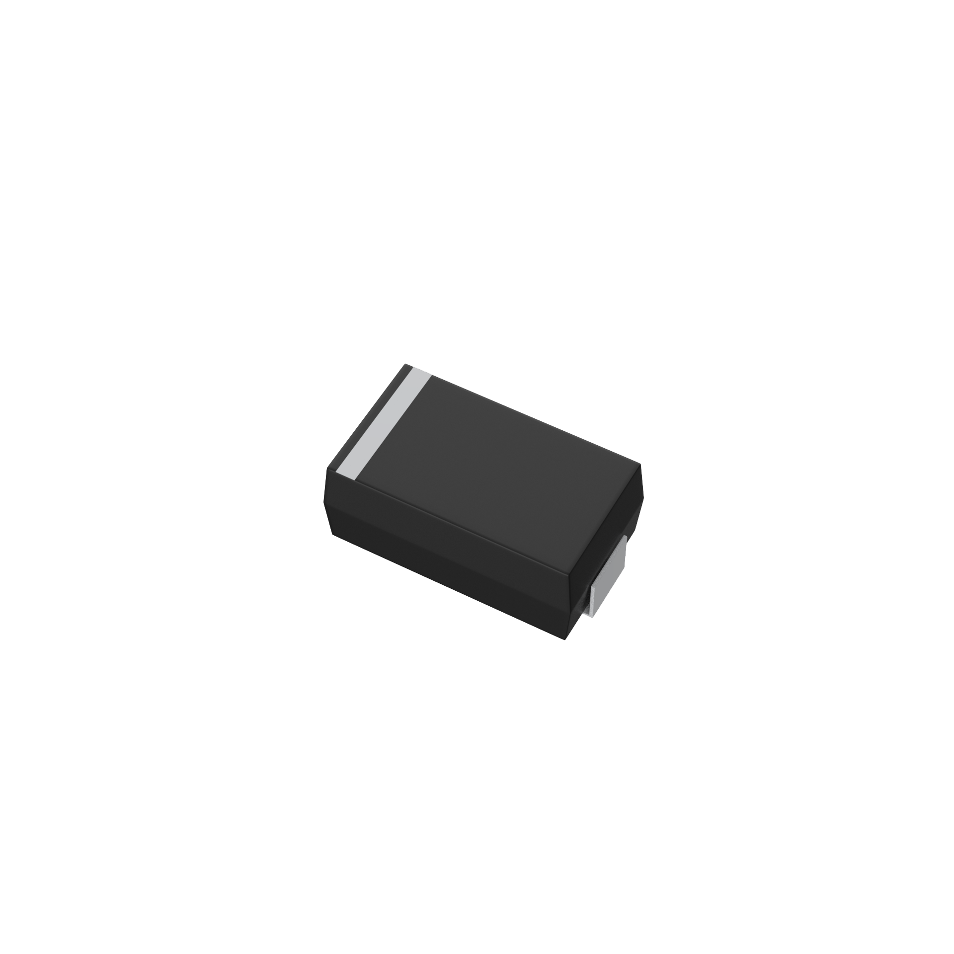
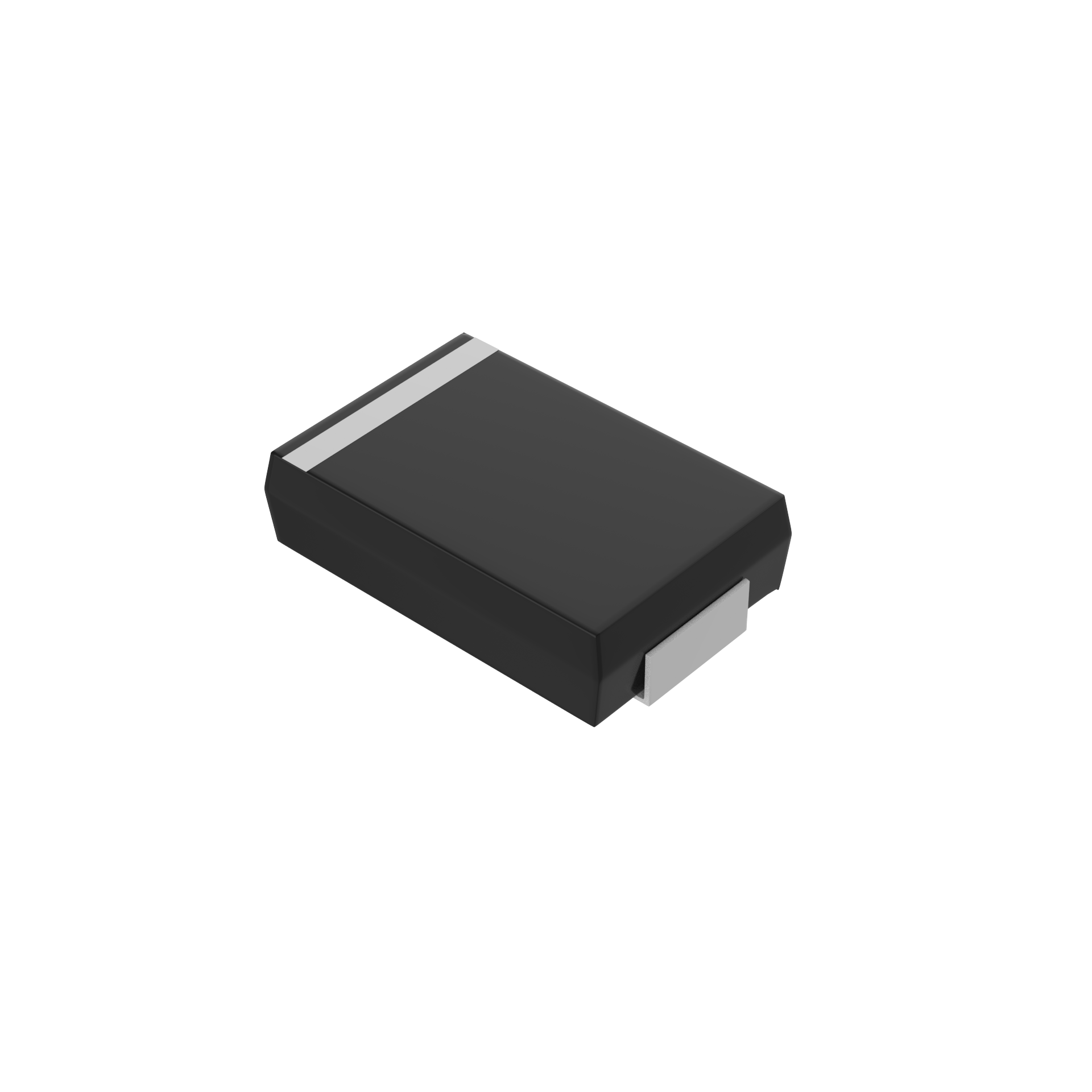
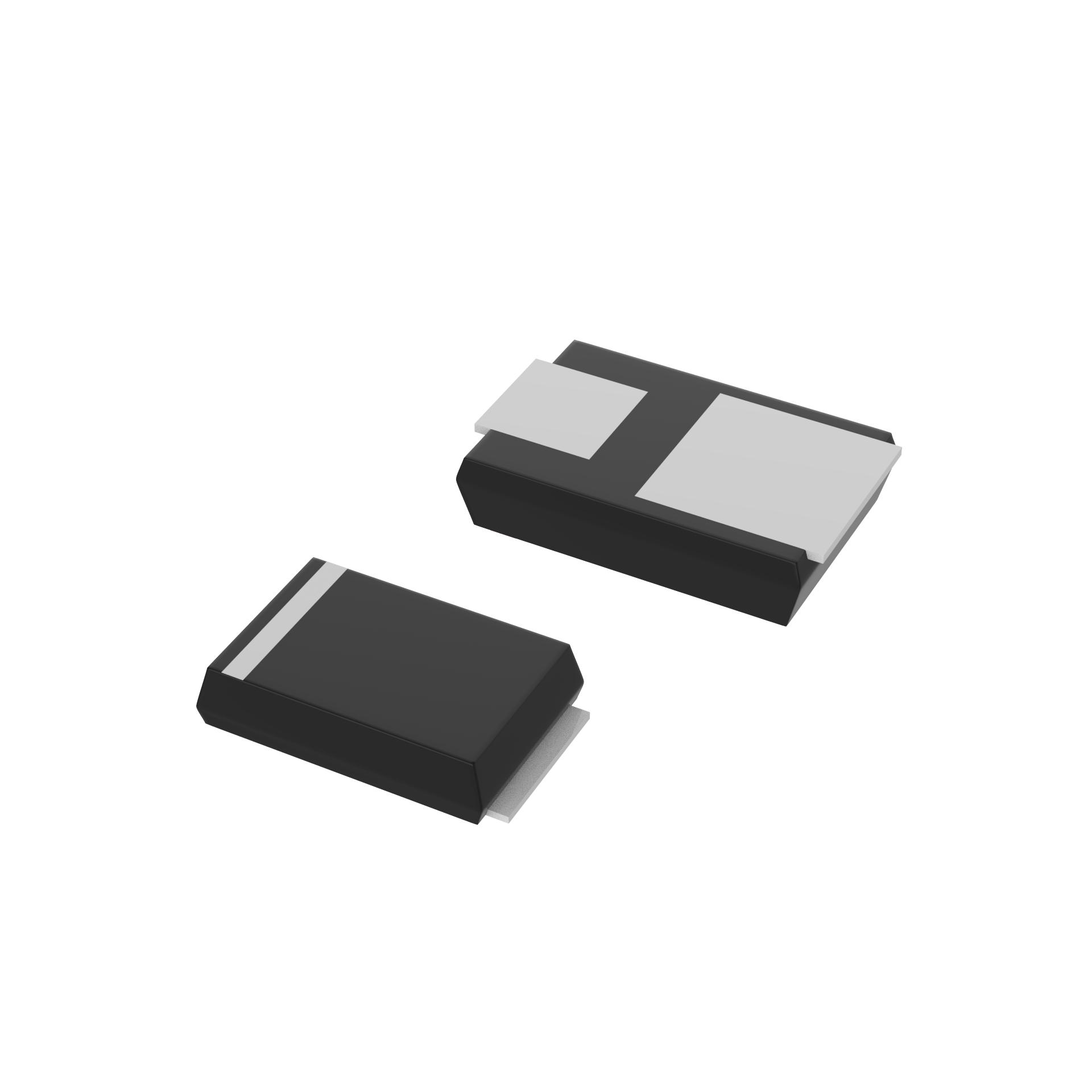
- Diod safonol y setiau/Schottky
- MOSFET rhial P-gyfer
- MOSFET rhial N-gyfer
2. Ymwybyddion Cyffredinol Arwain Dwylyd Cyfesurynnol
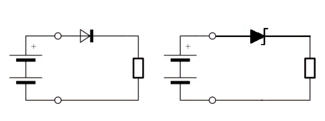
2.1 Dull Setiau Diode
Principiol sylfaenol: Mae diod safonol neu Schottky yn cael ei leoli mewn cyfres â'r rail grefydd positif ac mae'n llwgo yn unig pan mae'r polariti'n gywir.
Cyd-destun Technegol:
|
Math |
Swmpio Argyfwng (V) |
Manteision |
Anabuddion |
|
Diod Safonol |
0.7 ~ 1.0 |
Syml, cost yn isel |
Lwythfrydedd uchel, colli llawer o drefn |
|
Diod Schottky |
0.2 ~ 0.5 |
Lwythfrydedd isel, effeithlonrwydd uchel |
Amlwg fwy o arfwyddiaeth |
Gwneud defnydd: Arbrofiadau is-gyfradd, neu arbrofiadau sensitif i gost.
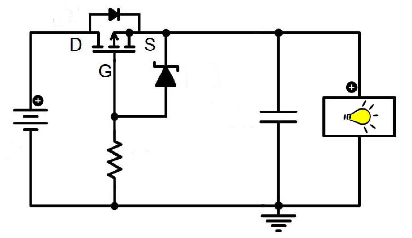
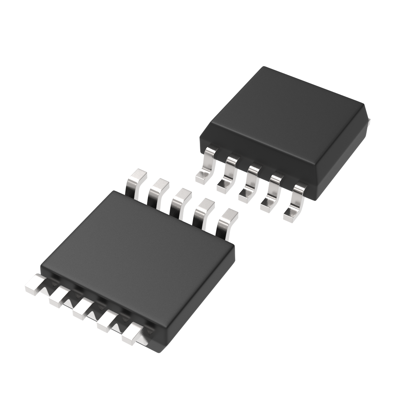
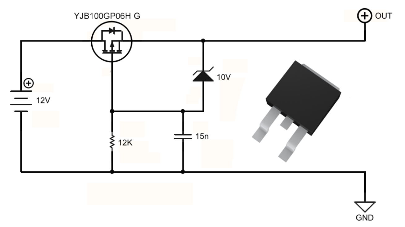
2.2 Ddatblygiad MOSFET Llwyfan P (Argymhellyd)
Strwythur Cylchyn: Mae MOSFET llwyfan P yn cael ei leoli yn gyfesurynnol â'r rail grefydd positiw, a thrwy ddefnyddio diod Zener i amgylchedd y gat.
Gynllun Gweithio:
- Pan mae'n cael ymateb yn gywir, mae'r didiod corff y MOSFET yn cyflwyno, ac mae'r terminal Ffynhonnell yn derbyn foltiwg bateri.
- Mae'r Gat ar 0V, yn ei gyffwrdd â Vgs yn nechyll, ac yn agor y MOSFET.
- Mae'r diod Zenydd yn cyfyngu Vgs i'w foltiad arosol.
Pryd yn bwrw'n wyneb: Mae'r diod corff yn beirniadu yn ôl, mae'r MOSFET yn gau, mae'r cylchyn yn brwnt, a mae'r system yn cael ei ddiogelu.
Pawblygiadau: Amheuaeth gorau llai wrth iddi fod yn agored, potensial llai o herwyddo gynulleidio na chynlluniau. Does dim ofynnwr allanol angen.
Defnydd: Yn gyffredinol yn cael eu defnyddio mewn electronig motorol, UCAs, a chylchoedd cynnar BMS.
2.3 Gweldyn MOS N-Dros (Uchelgais Uchelgeisiol)
Nodweddion:
- Rds(on) ishwel na'r gweldyn P-dros, addas ar gyfer systemau gyrfa uchel.
- Mae angen ddyfarn pump neu drydydd llif i leisio Vgs uwch na Ffynhonnell.
Yn y cysylltiad gyfan: Mae diod corff yn cael ei beirniadu yn erchyll, mae drïo'r gat wedi'i ansablhau, a'r gweldyn MOS yn aros yn ddigwydd.
Gymhlethdod: Addas ar gyfer systemau effeithlon uchel fel rheolwyr EV cynyddol.
2.4 Datrysiadau sy'n seiliedig ar reolydd: RPP vs Rheolwyr Diod Ideali
|
Mater rheolwr |
Nodweddion |
Gwrthgysylltu Corn |
|
Rheolwr RPP |
Mae'n gweithio gyda MOSFET N-fanel, yn darparu amddiffyniad polarrwydd gwrthdaro yn unig |
No |
|
Gynllunydd Diod Ideg |
Darparwyd diogelwch ar ôl cyfuniad + gwared ar droseddu amheusedd |
Ydw |
3. Dinamig vs Statig Ar ôl Cyfuniad
Ar Ôl Cyfuniad Statig: Cysylltiad ar ôl hir, mae angen amddiffyniad sylweddol.
Ar Ôl Cyfuniad Dynamig: Cysylltiad ar ôl cyfyngedig, er enghraifft trospledi llawer o waith, mae angen ymateb gyflym.
4. Amddiffyniad Rhelyg Gweithredol (Arbennig)
Manteision:
- Gallu cynyddu amperioedd uchel gyda chwympfiant ffon ar y cyfaint bachaf.
- Darparir toriadau llawn o'r cylchfan pan mae agored.
Anfanteision:
- Maint mawr, bys mesur yn bryderus.
- Ymateb llaeth, ddim addas i symudiadau gyffredin.
5. Crynodeb a Thywgraff Dewisiad
|
Math o Ddewisiad |
Defnydd o werin |
Cost |
Cyflymder Ymateb |
Amrediad Presennol |
Ymaterog Gweithred |
|
Diod Safonol/Schottky |
Canol i Uchel |
Isel |
Cyflym |
Isel i Canol |
Cylchoedd syml, systemau is-gyfradd |
|
P-Channel MOSFET |
Isel |
Canol |
Cyflym |
Canol i Uchel |
Pŵer arddull gyffredinol, diogelu BMS |
|
N-Channel MOSFET |
Ar ddiwedd lleiaf |
Canol |
Cyflym |
Uchel |
Rheoli pŵer uchel, modiwlau rheoli EV |
|
Gychwynnol-Weddi |
Isel |
Canol i Uchel |
Cyflym |
Canol i Uchel |
Ymyriadau presiwn, rheoli diwydiannol |
|
Relai |
Ar ddiwedd lleiaf |
Canol |
Llym |
Yn uchel iawn |
Isebyddu corfforol, amgylcheddau gyrfa mawr |