Understanding EMI and the Role of Filter Capacitors in Signal Integrity
Electromagnetic Interference (EMI) disrupts electronic systems by inducing unwanted voltage fluctuations, degrading signal accuracy in applications ranging from medical devices to automotive control modules. A 2022 study by the IEEE EMC Society found that 74% of signal integrity failures in mission-critical systems stem from inadequate EMI suppression.
The Impact of Electromagnetic Interference on Signal Integrity
High-frequency noise couples into signal paths through radiated emissions or conductive coupling, distorting waveforms and increasing bit error rates in communication protocols like PCIe and USB4. This interference often manifests as timing jitter, reduced signal-to-noise ratios, and false triggering in digital circuits.
How EMI Filter Capacitors Mitigate High-Frequency Noise
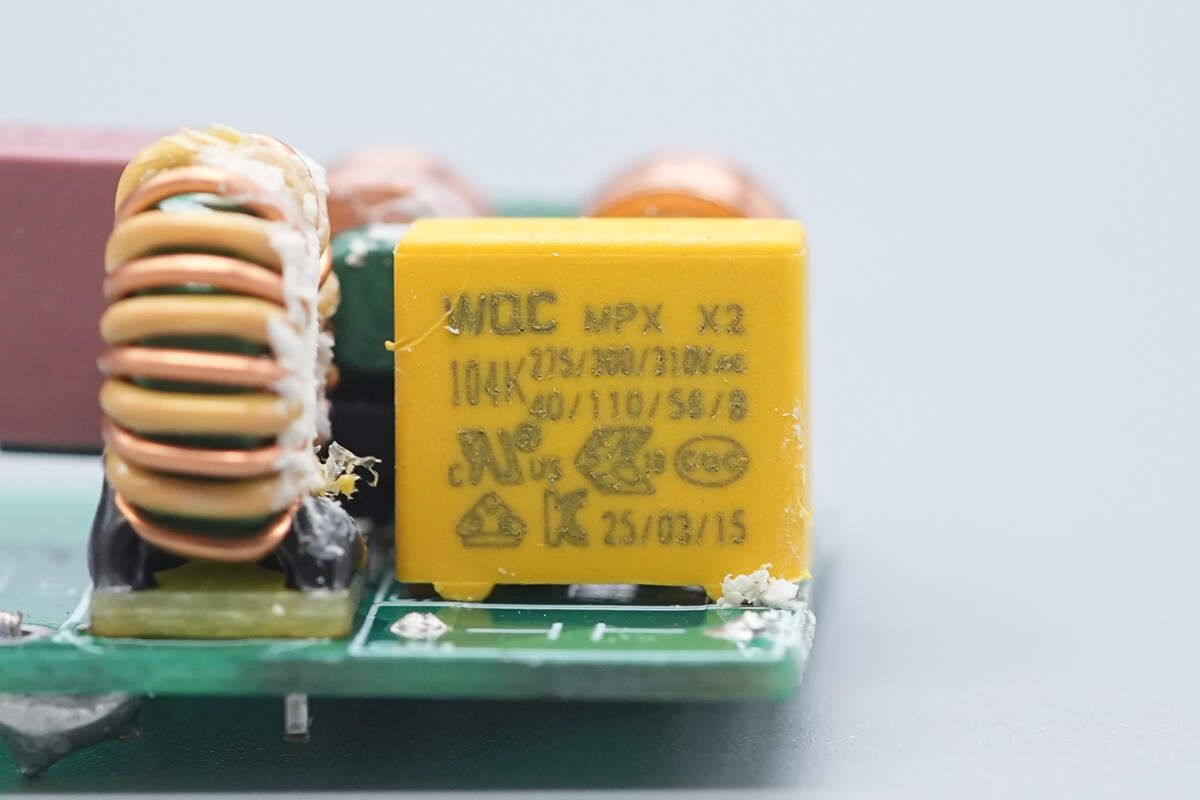
EMI filter capacitors work to cut down on electrical noise by creating a path to ground that has very low resistance for frequencies over around 1 MHz. Pair these with inductors and suddenly we get LC filters which can knock out those pesky unwanted signals quite effectively, sometimes reducing them by as much as 40 decibels. The good news is that this filtering doesn't mess with the main signal frequencies we actually want to keep intact. Take X2 safety capacitors used in AC to DC power supplies as a real world case. These components help eliminate common mode noise by basically redirecting those annoying interference currents so they don't bother the delicate control integrated circuits in the system.
Low Impedance Characteristics and Frequency Response of EMI Capacitors
Today's multilayer ceramic capacitors (MLCCs) can get down to under 0.5 ohms of impedance at 100 MHz thanks to those fancy C0G or NP0 dielectric materials. The really low impedance makes these components great for cutting down on electrical noise throughout the 150 kHz to 30 MHz spectrum that CISPR 32 standards require for emissions control. When engineers need broadband noise suppression, they typically throw several different capacitor values together in parallel circuits. This approach works because each capacitor handles a different part of the frequency range, creating coverage where single components would fall short.
Common-Mode vs. Differential-Mode Noise in Electronic Systems
- Common-mode noise flows between power/ground lines and earth, typically addressed with Y-class capacitors
- Differential-mode noise appears between power line conductors, mitigated through X-class capacitors and series inductors
Effective EMI filtering requires identifying noise type through spectral analysis before selecting capacitor classes and filter topologies.
Key Mechanisms: How EMI Filter Capacitors Suppress Noise and Protect Signals
Capacitors Shunting High-Frequency Noise to Ground
EMI filter capacitors work by creating paths with very low resistance that pull away those pesky high frequency noises above around 1 MHz before they can bother sensitive parts of a circuit. When connected across power lines and earth ground, these components basically act as shortcuts for interference signals, cutting down on transmitted electromagnetic pollution by somewhere in the ballpark of 40 decibels. The whole process works really well for filtering out AC line noise too. Special X and Y rated safety capacitors handle both types of interference at once differential mode and common mode stuff while still staying within required safety limits for electrical equipment.
Decoupling and Bypassing in Power and Signal Lines
Decoupling capacitors isolate power rail fluctuations from integrated circuits (ICs), while bypass capacitors redirect high-frequency transients (5–500 MHz) to ground. Placing 100 nF ceramic capacitors within 2 cm of IC power pins reduces voltage spikes by 75%. This dual approach stabilizes supply voltages in digital systems and prevents crosstalk in mixed-signal designs.
Optimal Placement of Capacitors Near Noise Sources
Strategic capacitor placement reduces parasitic inductance by 60–80% compared to distant mounting. For example:
- Placing 10 µF tantalum capacitors within 5 mm of switching regulators suppresses 90% of ripple noise
- Mounting 1 nF film capacitors directly at motor driver outputs attenuates brush noise by 20 dB
Proximity ensures effective filtering up to 1 GHz, critical in RF and high-speed PCB layouts.
Combining Ceramic and Film Capacitors for Broadband Suppression
| Capacitor Type | Effective Range | Attenuation |
|---|---|---|
| Multilayer Ceramic | 1 MHz – 2 GHz | 30–50 dB |
| Polypropylene Film | 10 kHz – 10 MHz | 40–60 dB |
Hybrid configurations leverage ceramic capacitors’ high-frequency performance and film capacitors’ stability under high voltage (up to 1 kV). This combination provides 98% noise attenuation across 10 kHz–5 GHz spectra in aerospace communication systems.
EMI Filters: Integrating Capacitors for Comprehensive Interference Suppression
Modern EMI filters combine capacitors with inductors and resistors to create multi-stage noise suppression systems. These filters achieve 60–100 dB attenuation across critical frequency ranges through strategic component interactions.
Core Components of EMI Filters and Their Interaction With Capacitors
Capacitors serve as the primary high-frequency shunt elements in EMI filters, working synergistically with inductors that block common-mode noise. This layered approach enables 3-stage filtering:
- Input capacitors suppress differential-mode interference
- Inductors create impedance barriers for conducted emissions
- Output capacitors address residual high-frequency noise
Frequency Response and Attenuation Characteristics of EMI Filters
Proper capacitor selection determines a filter's frequency roll-off characteristics. X2 safety capacitors (400–630 VAC rated) typically provide 100 nF–4.7 µF capacitance for 10 kHz–30 MHz noise suppression, while Y1 capacitors (250 VAC) handle higher frequencies up to 1 GHz. Filters combining ceramic and film capacitors achieve 120 dB/decade attenuation slopes.
Matching Filter Bandwidth to Interference Spectrum
Engineers use impedance analyzers to map capacitor performance against specific EMI profiles. Optimal filters maintain <1 dB insertion loss at operating frequencies while providing >40 dB rejection at EMI harmonics. Market demand for spectrum-specific solutions in EV charging and medical devices is driving innovation in targeted suppression technologies.
Miniaturization Trends in EMI Filter Design Without Performance Loss
Advanced MLCC technologies enable 0402-size components (0.4–0.2 mm) with 100 nF capacitance and 6.3–100 V ratings. Stacked film capacitors now achieve 94% volumetric efficiency improvements compared to 2020 designs, enabling compact filter footprints below 10 mm³–critical for 5G infrastructure and implantable medical devices.
Real-World Applications: EMI Capacitors in High-Speed and Power Electronics
Improving Signal Integrity in High-Speed PCBs with EMI Filtering
For today's fast paced PCBs, EMI filter capacitors play a big role in keeping signals clear by cutting down on noise frequencies over 1 GHz. This is really important stuff when it comes to building out 5G networks and those powerful computers we rely on. Engineers have found that when they set up multi stage filters with those special ceramic caps that have super low inductance around or below 0.5 nH, they can slash crosstalk problems in DDR5 memory systems by about two thirds. The numbers come from research presented at the IEEE Signal Integrity Symposium back in 2023, which makes sense given how crucial clean signals are becoming as data rates keep climbing.
Reducing Bit Error Rates in Communication Systems
X2Y® capacitor arrays suppress common-mode noise in differential signaling paths, reducing bit error rates (BER) in 25Gbps optical transceivers to <10⁻¹². These components effectively dampen resonance caused by parasitic inductances in power-over-fiber systems.
Enhancing Gate Driver Signals in IGBT and Power Converter Modules
High-frequency SiC-based power modules require capacitors with:
| Parameter | Requirement | Typical Solution |
|---|---|---|
| Switching Speed | <50 ns | GaN-optimized MLCCs |
| Voltage Rating | ≥1.2 kV | Stacked ceramic arrays |
| Ripple Current | ≥30 A RMS | Hybrid film-ceramic |
Such configurations suppress transient spikes in 100 kW industrial motor drives by 42% while maintaining <2% signal distortion.
Ensuring Reliability in EV Charging Stations and Medical Devices
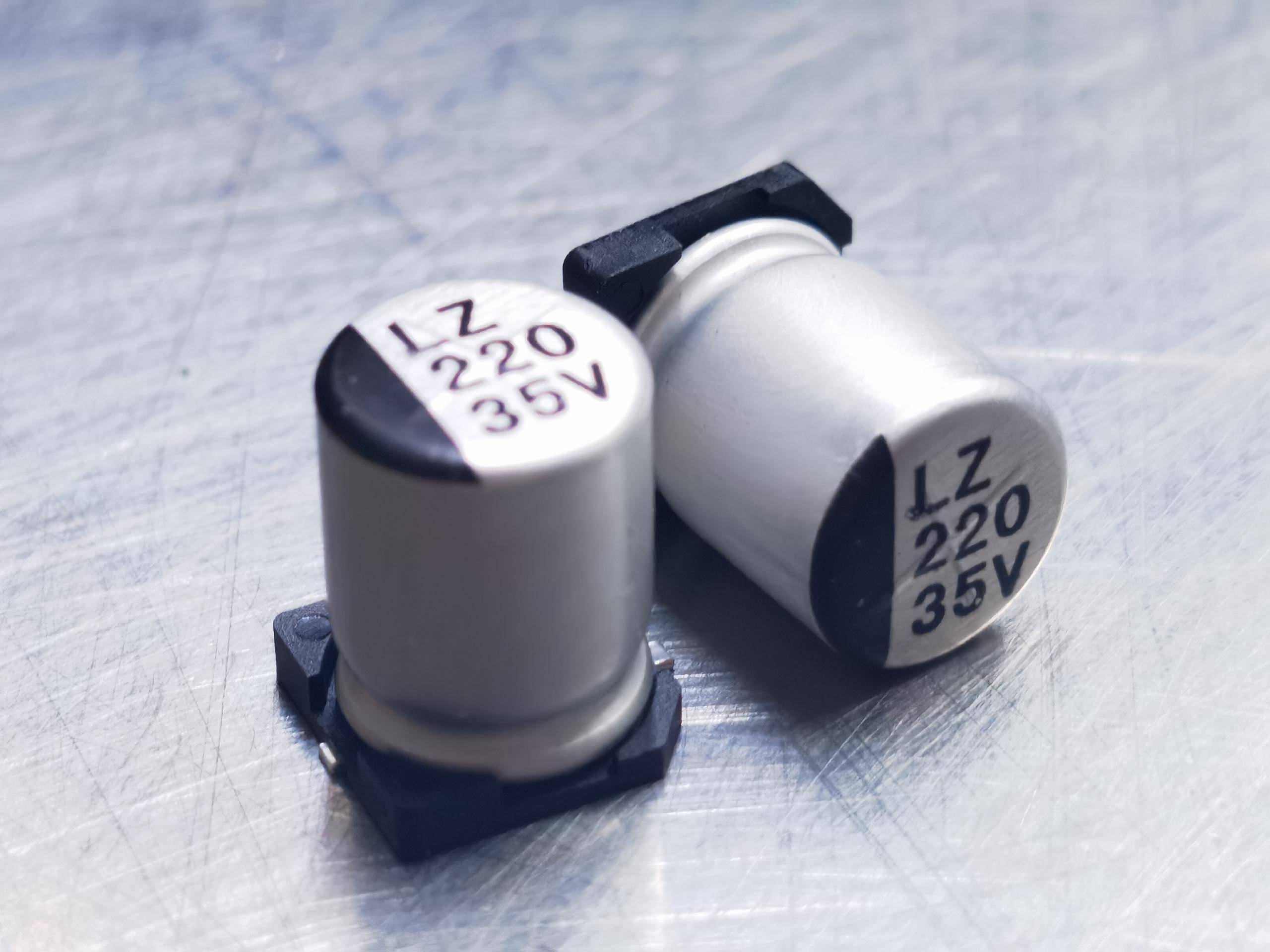
Medical imaging equipment and 350 kW EV chargers utilize aluminum electrolytic capacitors with:
- 200,000-hour operational lifespan at 105° C
- ≤10 mΩ equivalent series resistance (ESR)
- Safety certifications per IEC 60384-14
These components filter leakage currents below 100 µA in defibrillators while handling 800V DC bus voltages in next-gen EV infrastructure. The global market for such applications is projected to grow at 7.08% CAGR through 2032.
Best Practices for Selecting and Implementing EMI Filter Capacitors
Choosing Capacitors Based on Frequency Range and Noise Type
Getting good EMI suppression starts when we match capacitor characteristics to what kind of interference we're dealing with. For those high frequency noises above 1 MHz, ceramic capacitors with X7R or C0G dielectrics work best because they have low inductance. On the other hand, film capacitors are better suited for handling the lower frequency noise from switched mode power supplies. When engineers actually take the time to match their capacitors' frequency response curves with the specific interference patterns present in a system, they can cut down conducted emissions anywhere between 18 and 25 dB micro volts. That's quite a difference compared to just throwing in whatever capacitors happen to be available off the shelf.
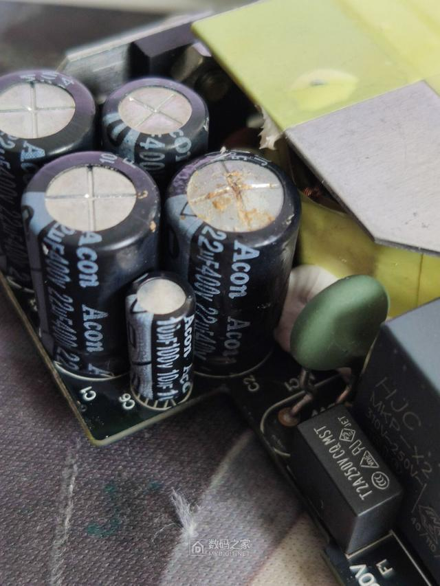
Comparative Use of X and Y Safety Capacitors in AC Line Filtering
X capacitors (line-to-line) and Y capacitors (line-to-ground) form the backbone of AC line filtering. X-class components suppress differential-mode noise between live and neutral conductors, while Y-class capacitors address common-mode interference. Coordinated X/Y capacitor networks achieve over 30% improvement in conducted EMI suppression versus standalone configurations.
Integrating EMI Capacitors into Compact and Modular Designs
Modern power electronics demand capacitor arrays with 0402 case sizes (1.0 x 0.5 mm) for direct integration into IC packages. Multi-layer ceramic capacitors (MLCCs) now provide 100 nF–10 µF filtering in 3D-printed shielding cavities, maintaining 50 Ω impedance up to 6 GHz.
Balancing Capacitor Size, Cost, and Filtering Efficiency
Implement an 85% performance baseline–oversized capacitors beyond 2x the calculated suppression requirement yield <5% additional attenuation while increasing costs by 40–60%. Iterative testing with vector network analyzers optimizes this balance through impedance/frequency mapping.
Frequently Asked Questions (FAQ)
What is Electromagnetic Interference (EMI)?
Electromagnetic Interference (EMI) refers to disruption caused by electromagnetic fields affecting electronic circuits, which can degrade signal integrity and lead to system malfunctions.
How do EMI filter capacitors improve signal integrity?
EMI filter capacitors improve signal integrity by shunting unwanted high-frequency noise to the ground, allowing the main signal frequencies to remain intact.
What types of noise do capacitors handle in electronic systems?
Capacitors handle common-mode noise, which flows between power/ground lines and earth, and differential-mode noise, which appears between power line conductors.
What are X-class and Y-class capacitors?
X-class capacitors are used for suppressing differential-mode noise, while Y-class capacitors address common-mode interference in AC line filtering.
What factors should be considered when selecting EMI filter capacitors?
The selection of EMI filter capacitors should consider the frequency range, noise type, and the specific interference patterns present in the electronic system.
Table of Contents
- Understanding EMI and the Role of Filter Capacitors in Signal Integrity
- Key Mechanisms: How EMI Filter Capacitors Suppress Noise and Protect Signals
- EMI Filters: Integrating Capacitors for Comprehensive Interference Suppression
- Real-World Applications: EMI Capacitors in High-Speed and Power Electronics
- Best Practices for Selecting and Implementing EMI Filter Capacitors
- Frequently Asked Questions (FAQ)