How Bridge Rectifiers Enable Efficient AC to DC Conversion
Definition and Function of Bridge Rectifiers
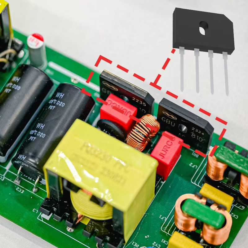
A bridge rectifier basically consists of four diodes set up like a diamond shape to turn AC electricity into DC. The way it works is pretty clever actually - it sends each half of the AC wave through different diodes so we get steady current coming out the other end, and best part? No need for those complicated center tapped transformers anymore. These little gadgets show up everywhere from phone chargers to industrial motor controls wherever someone needs reliable direct current instead of fluctuating alternating current.
Working Principles of Rectifiers in Power Conversion
When dealing with AC input, things get interesting during those half-cycles. The positive half-cycle sees D1 and D3 doing most of the work, while their counterparts D2 and D4 step in when the cycle turns negative. This back-and-forth action keeps current flowing consistently through the load in just one direction, turning both parts of that AC signal into what we call pulsating DC. Full wave operation actually works twice as fast as half wave setups, which means better efficiency overall and less annoying ripple in the output. But there's always a catch. Those silicon diodes create a voltage drop around 1.4 volts typically, and this leads to some power loss plus heating issues that engineers need to watch out for in real world applications.
Full-Wave Rectification vs. Half-Wave: Why Bridge Rectifiers Dominate
Bridge rectifiers work better than their half-wave counterparts because they actually use both halves of the AC cycle instead of just sitting there doing nothing on one phase. This gives them around 40% more efficiency overall while producing much less ripple at the output end. Half-wave versions tend to waste energy when they're not active, especially under lighter loads where efficiency drops below 60%. Bridge rectifiers keep things running smoothly between 75% to 85% efficiency most of the time though. What makes these even more useful is how well they pair with capacitors and other filters to stabilize the output voltage. That's why we see them everywhere from hospital equipment needing reliable power to those fancy LED driver circuits in modern lighting systems and all sorts of sensitive electronic gear.
Circuit Design and Diode Configuration in Bridge Rectifiers
Bridge Rectifier Circuit Configuration and Component Layout
The basic bridge rectifier circuit typically consists of four diodes arranged in what looks like a diamond shape when drawn out on paper. When we talk about how it works, AC power comes into two opposite points of this configuration, and then DC electricity gets pulled out from the other two connection points. For good performance, engineers usually make sure all those diodes match each other pretty closely. There's also always a load resistor somewhere in there, plus sometimes folks throw in a capacitor to smooth things out if needed. What makes this setup so popular among designers is that it allows full wave rectification without needing that complicated center tapped transformer. The result? Simpler designs overall and generally lower costs compared to alternative approaches.
Diode-Based Rectifiers: Role of PN Junctions in Full-Wave Operation
The PN junction inside each diode acts kind of like a one way gate, letting current flow through it only when it's forward biased. During the positive part of an AC waveform, one set of diagonally placed diodes will conduct electricity while during the negative phase, the opposite pair takes over. This back and forth switching keeps the output polarity stable regardless of which direction the input current is flowing. According to studies published by Power & Beyond, this constant switching actually makes the output frequency twice what it would be otherwise, which means filters downstream can do their job much better since there's less ripple to deal with in the signal.
Analysis of Diode Arrangement in Bridge Rectifiers for Optimal Current Flow
The bridge topology ensures optimal performance through:
- Two-diode conduction per half-cycle
- Peak Inverse Voltage (PIV) equal to √2 × V_input across non-conducting diodes
- Even thermal distribution across all junctions
This setup minimizes transformer saturation risks and achieves 98–99% conduction efficiency in standard 50/60Hz applications.
Design Trade-Offs: Simplicity vs. Thermal Management Challenges
Despite their circuit simplicity, bridge rectifiers face thermal limitations due to inherent voltage drops. At higher currents, power dissipation increases linearly:
| Load Current | Power Dissipation | Thermal Solution Required |
|---|---|---|
| 1A | 1.4W | Passive heatsinking |
| 5A | 7W | Active cooling |
| 10A | 14W | Liquid cooling |
Industry data indicates 68% of failures stem from poor thermal design, underscoring the importance of proper heatsinking and airflow in high-current systems.
Efficiency and Performance of Bridge Rectifiers in Real-World Applications
Efficiency of power conversion in rectifiers: Measuring performance gains
Bridge rectifiers improve efficiency by processing both halves of the AC waveform, cutting ripple voltage by more than 50% compared to half-wave designs. This allows simpler filtering and delivers cleaner DC output suitable for sensitive electronics.
Voltage drop and losses in standard silicon diode bridges
Silicon diodes typically exhibit 0.7–1.2V drop per conducting pair, leading to fixed conduction losses. At 10A, these losses account for 12–18% of total energy dissipation, directly impacting system efficiency—especially in high-power or low-voltage applications.
Typical efficiency range (75–85%) in industrial SMPS units
In switched-mode power supplies (SMPS), conventional bridge rectifiers achieve 75–85% efficiency under full load. According to recent power electronics research, thermal constraints cap peak efficiency around 82% in actively cooled units, highlighting the need for advanced thermal management.
Are bridge rectifiers still efficient at low loads?
Efficiency drops to 50–65% at 10–20% load due to fixed diode losses dominating over reduced output power. To address this, modern designs incorporate adaptive control and synchronous rectification, maintaining over 70% efficiency across variable loads.
Advanced Types of Bridge Rectifiers: From Schottky to Synchronous Designs
Modern power systems use specialized rectifier types to meet demands for higher efficiency, better thermal performance, and application-specific functionality.
Types of Bridge Rectifiers: Schottky, SCR, MOSFET, and Synchronous Variants
| Type | Key Feature | Typical Application | Efficiency Gain* |
|---|---|---|---|
| Schottky | 0.3 V forward voltage drop | Low-voltage SMPS | 4-7% vs silicon |
| SCR | Thyristor-based current control | Industrial motor drives | 82-89% range |
| MOSFET | Voltage-controlled switching | High-frequency converters | 91-94% |
| Synchronous | Active transistor rectification | Server PSUs, EV chargers | ≈96% |
*Based on 2023 IEEE Power Electronics Society benchmarks
Schottky Bridge Rectifiers: Advantages in Low Forward Voltage Applications
Schottky diodes reduce conduction losses by 40–60% thanks to their metal-semiconductor junctions. A 2023 materials study found optimized Schottky bridges maintain under 0.3V drop at 10A, making them well-suited for 5G infrastructure and LED lighting, where heat generation must be minimized.
SCR-Based Bridges for Controlled Rectification in High-Power Systems
Silicon-controlled rectifiers (SCRs) enable precise regulation in high-power environments such as electric arc furnaces and traction systems. Gate-triggered operation allows phase-angle control, which reduces harmonic distortion by 18–22% in three-phase industrial setups, improving grid compatibility and system longevity.
Emerging Trend: Synchronous Rectifiers Replacing Diodes in High-Efficiency Designs
Synchronous rectifiers using MOSFETs eliminate the fixed voltage drop of diodes, achieving up to 94% efficiency in 1kW server power supplies. They also reduce thermal stress by up to 30°C, enabling compact designs in USB-PD chargers, automotive onboard units, and IoT devices.
Key Applications and System Integration of Bridge Rectifiers
Applications in Power Electronics: Adapters, Motor Drives, and UPS Systems
Bridge rectifiers play a really important role in today's power electronics world. When it comes to adapters, these components take the standard AC electricity from wall outlets and turn it into the lower voltage DC needed for all our gadgets and devices. For industrial applications like motor drives, bridge rectifiers help cut down on something called torque ripple which makes machines run smoother and last longer, some studies even suggest improvements around 70% in certain cases. Another place where we find bridge rectifiers working hard is in those backup power systems known as UPS units. They keep batteries charged when everything's running normally, but what people might not realize is how critical they become during power outages, maintaining stable voltage levels so equipment doesn't get damaged.
Role in Renewable Energy Systems: Solar Inverters and Wind Turbine Converters
In solar inverters, bridge rectifiers interface photovoltaic arrays with grid-tie systems, supporting up to 98% MPPT accuracy. Wind turbine converters increasingly use silicon-carbide-based bridges to manage variable-frequency outputs, boosting energy capture by 12–18% in turbulent conditions. Integrated rectifier-filter modules have been shown to reduce harmonic distortion by 41% in large-scale offshore installations.
Integration with Filtering Techniques: Capacitor and Active Filtering Solutions
To deliver clean DC output, bridge rectifiers are paired with filtering solutions tailored to application needs:
| Filter Type | Ripple Reduction | Use Case Example |
|---|---|---|
| Electrolytic Caps | 85-92% | Consumer electronics adapters |
| LC Networks | 93-97% | Industrial motor controllers |
| Active PFC Circuits | 99%+ | Server-grade PSUs |
Emerging active filters using gallium-nitride (GaN) switches suppress noise above 150kHz, enabling >99% efficiency in high-density data center power systems.
FAQ
What is a bridge rectifier, and how does it work?
A bridge rectifier is a device that converts alternating current (AC) to direct current (DC) using four diodes arranged in a diamond shape. It allows both halves of the AC waveform to be used effectively, resulting in a consistent DC output.
Why are bridge rectifiers preferred over half-wave rectifiers?
Bridge rectifiers are more efficient than half-wave rectifiers because they utilize both halves of the AC cycle, providing a more stable and efficient DC output. They also produce less ripple and energy waste.
What are some common applications of bridge rectifiers?
Bridge rectifiers are commonly used in phone chargers, industrial motor controls, power adapters, motor drives, UPS systems, solar inverters, and wind turbine converters.
How do bridge rectifiers impact energy efficiency?
Bridge rectifiers improve energy efficiency by processing the entire AC waveform, reducing ripple voltage, and requiring simpler filtering. They typically achieve efficiencies between 75% to 85% in industrial applications.
What are some advanced types of bridge rectifiers?
Advanced types of bridge rectifiers include Schottky diodes, SCRs, MOSFET-based rectifiers, and synchronous designs. These variants offer different advantages, such as lower voltage drops and higher efficiency.
Table of Contents
- How Bridge Rectifiers Enable Efficient AC to DC Conversion
- Circuit Design and Diode Configuration in Bridge Rectifiers
- Efficiency and Performance of Bridge Rectifiers in Real-World Applications
-
Advanced Types of Bridge Rectifiers: From Schottky to Synchronous Designs
- Types of Bridge Rectifiers: Schottky, SCR, MOSFET, and Synchronous Variants
- Schottky Bridge Rectifiers: Advantages in Low Forward Voltage Applications
- SCR-Based Bridges for Controlled Rectification in High-Power Systems
- Emerging Trend: Synchronous Rectifiers Replacing Diodes in High-Efficiency Designs
- Key Applications and System Integration of Bridge Rectifiers
- FAQ