This page presents essential design principles for varistor (MOV) circuits, including selection tips, voltage configuration, protection strategies, and PCB layout advice—ideal for engineers building effective surge suppression and circuit protection solutions.
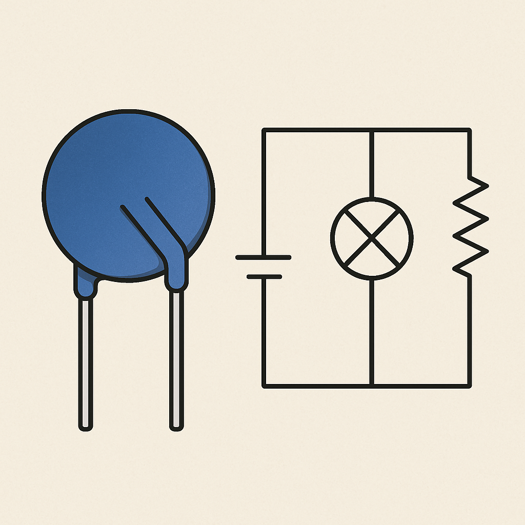
A Metal Oxide Varistor (MOV) is a nonlinear resistor whose resistance changes with the applied voltage. It is widely used in surge suppression, circuit protection, and the safety design of electrical equipment. To ensure its reliable and effective performance in a circuit, the following key principles should be followed when designing varistor-based circuits:
1. Select the Appropriate Varistor
Select a suitable varistor based on the application scenario (e.g., surge protection, power input protection, sensor circuitry). Key parameters include:
Clamping voltage (Vclamp)
Surge current capability (Imax)
Response time (<1 ns)
Static resistance and leakage current characteristics
2. Define the Operating Voltage Range
The normal operating voltage in the circuit should be lower than the varistor’s breakdown voltage but higher than its maximum continuous operating voltage (VMAC/VMDC) to avoid false triggering or failure.
3. Evaluate Circuit Impact
In high-frequency or precision circuits, MOVs may introduce capacitance, inductance, or leakage current. Watch for:
High-frequency response degradation
Thermal drift
Signal integrity disruption
4. Add Overvoltage Protection Measures
Combine MOVs with fuses, PTC thermistors, or TVS diodes to enhance protection and prevent damage or degradation under overload conditions.
5. Ensure Stable Power Supply Design
Use voltage regulators and EMI filters to ensure a stable, low-noise power supply, preventing power fluctuations from affecting MOV performance.
6. Optimize PCB Layout and Wiring
Place MOVs close to the protected components and away from heat or EMI sources. Use short, low-impedance paths and ensure good grounding to avoid parasitic effects.
7. Conduct Validation Testing and Debugging
After design completion, perform electrical and surge testing to validate the MOV’s behavior and circuit reliability. Use test results to refine the design.
Conclusion
As a critical protection component in electronic systems, proper selection and design of MOVs can significantly improve system safety and stability. In real-world applications, MOVs should be used together with TVS diodes, fuses, and filters to build a comprehensive protection solution.