A complete guide to NTC and PTC thermistor types, parameters, working principles, and circuit applications. Covers temperature sensing and inrush current limiting designs. Ideal for use in power supplies, temperature control, home appliances, and industrial systems.
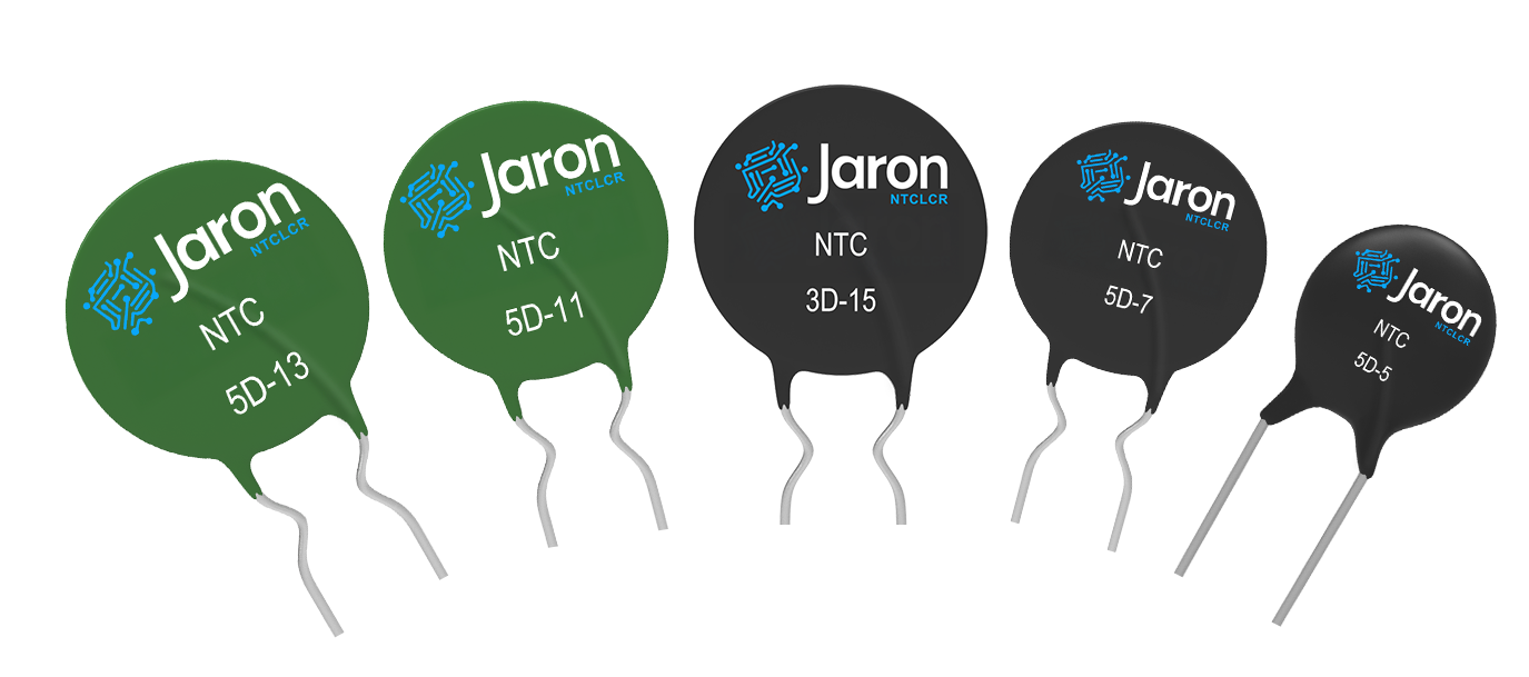
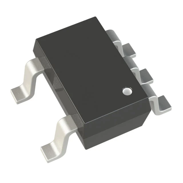
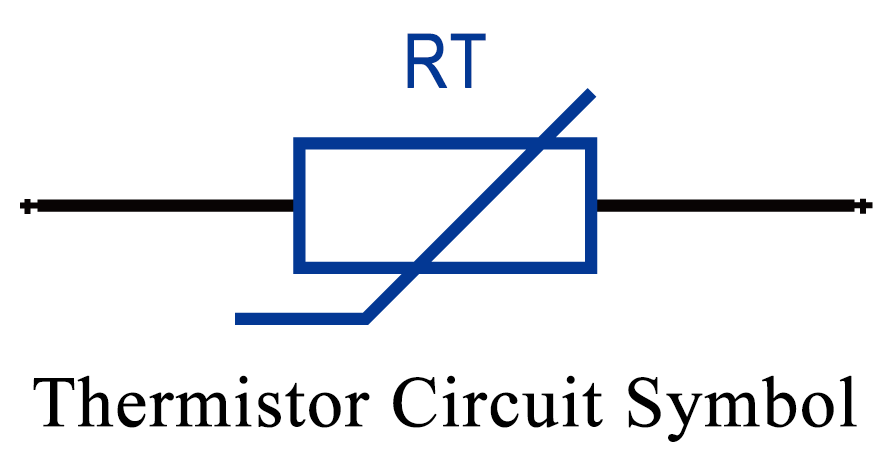
In circuit diagrams, thermistors are represented by specific symbols, and their physical form appears as shown in the illustrations.
1. Classification of Thermistors
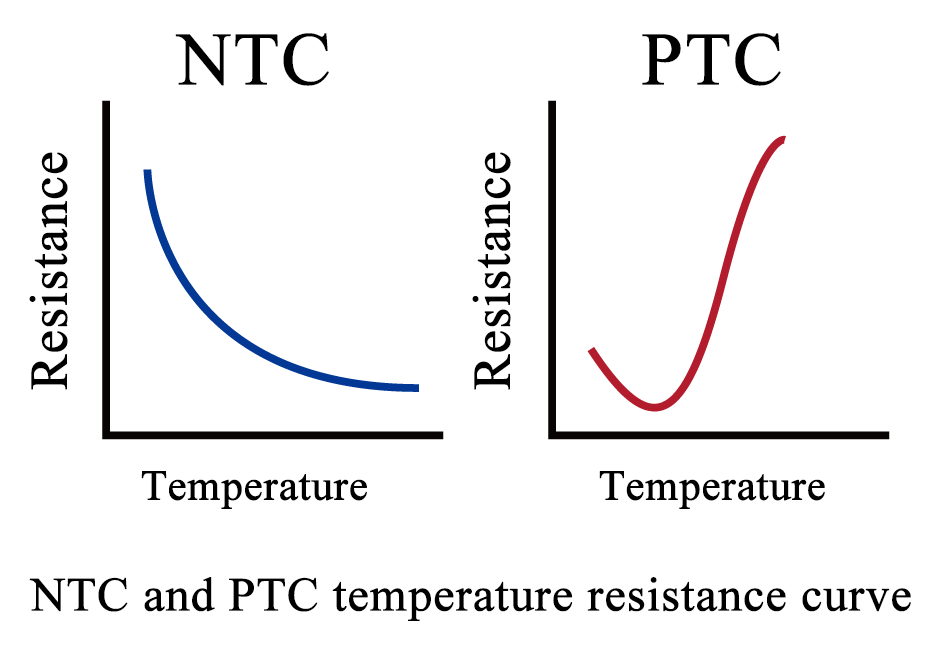
Positive Temperature Coefficient (PTC) Thermistor: The resistance of a PTC thermistor increases significantly as the temperature rises. Due to this property, PTC thermistors are commonly used in applications such as resettable fuses and heating elements.
Negative Temperature Coefficient (NTC) Thermistor: These thermistors exhibit a rapid decrease in resistance with increasing temperature. They are widely employed in temperature compensation circuits, thermal control systems, and surge current suppression.
The graph below compares the resistance-temperature curves of NTC and PTC thermistors.
2. Key Parameters of Thermistors
Rated Zero-Power Resistance R<sub>25</sub> (Ω)
As defined by national standards, this is the resistance value measured at 25°C in the absence of any applied power. This value is also known as the nominal resistance and is commonly referred to when specifying an NTC thermistor’s resistance.
Thermal B Constant (K)
The B value quantifies the thermistor’s sensitivity to temperature and is calculated as the ratio of the natural logarithm of resistance at two temperatures to the difference of the inverse of those temperatures. Once defined, it remains fixed. Typical B values for NTC thermistors range from 2000K to 6000K. Higher values indicate greater resistance sensitivity to temperature changes.
Dissipation Factor (δ)
This factor represents the ratio of the change in power dissipated to the resulting change in the thermistor’s body temperature under specified environmental conditions.
Thermal Time Constant (T)
Under zero-power conditions, it is the time required for the thermistor to reach 63.2% of the total temperature change after a sudden temperature variation. This constant is directly proportional to the thermistor’s thermal capacity and inversely proportional to its dissipation factor.
Rated Power (P)
This is the maximum continuous power the thermistor can dissipate under defined conditions without its body temperature exceeding the specified maximum operating limit.
Maximum Operating Temperature (Tmax)
The highest temperature at which the thermistor can operate continuously without performance degradation under defined technical parameters.
3. Practical Circuit Applications
NTC thermistors are commonly used in two major application categories: temperature sensing and power protection.
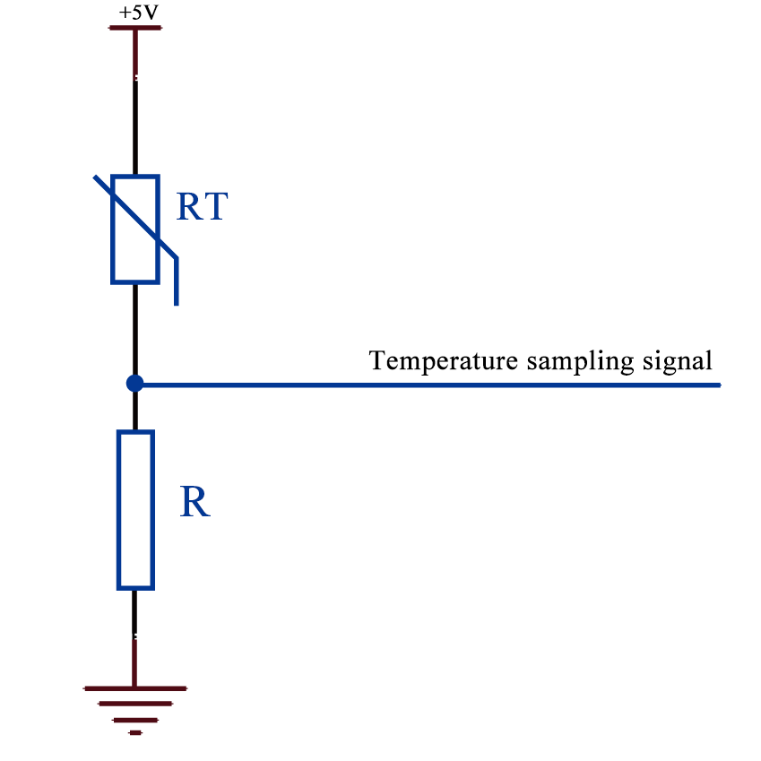
Example 1: Temperature Sampling Circuit
Example 2: Inrush Current Suppression
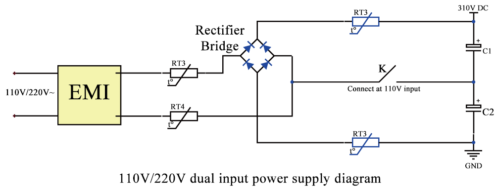
NTC thermistors are often placed at the power input stage, as shown in positions RT1 to RT4 in the circuit diagram. For devices that support both 110Vac and 220Vac inputs, two NTC thermistors should be placed at positions R1 and R2 to ensure consistent surge protection. In single-voltage (220Vac) systems, one NTC thermistor at either R3 or R1 is sufficient.
Operating Principle:
When powered on, bulk capacitors in the power supply cause a large inrush current. An NTC thermistor with a high initial resistance (at room temperature) can effectively limit this current. As current flows, the thermistor heats up rapidly and its resistance drops within milliseconds to a few ohms or less. This drop has minimal effect on the operational current, and its power consumption is negligible.
Compared to fixed resistors, this approach reduces power dissipation by tens to hundreds of times, making it especially suitable for energy-efficient and high-performance applications like switching power supplies.
After the power is turned off, the thermistor gradually cools down, and its resistance returns to the initial zero-power value. When power is reapplied, the same suppression cycle is repeated.