NTC thermistor (NTC is the abbreviation of Negative Temperature Coefficient) is ahigh-density semiconducting ceramic element made of high-purity Mn,Co,Ni,Feand other oxidizing substances at high temperature.The basic characteristic is i...
NTC thermistor (NTC is the abbreviation of Negative Temperature Coefficient) is ahigh-density semiconducting ceramic element made of high-purity Mn,Co,Ni,Feand other oxidizing substances at high temperature.The basic characteristic is itsresistance value As the temperature increases and decreases,NT thermistors can bewidely used in temperature measurement,temperature compensation,and surgecurrent suppression.The main technical parameters of NTC thermistor
Rated zero power resistance value R25(Ω)
The rated zero power resistance value is the resistance value R25 measured by theNTC thermistor at a reference temperature of 25°℃.This resistance value is thenominal resistance value of the NTC thermistorB value(K)
The B value reflects the resistance bending between two temperatures
The B value is defined as:![]()
RT1:Zero power resistance value at temperature T1(K).R12:Zero power resistancevalue at temperature T2(K)
T1 and T2 are two designated temperatures
Dissipation coefficient(δ)
Under the specified ambient temperature,NTC thermistor dissipation factor is the ratio of the power dissipated in the resistor to the corresponding temperaturechange of the resistor
NTC thermistor dissipation factor (mW/K).P:Power consumed by NTCthermistor(mW)
T:When NTC thermistor consumes power P,the corresponding temperature change (K) of the resistor body.
Thermal time constant(T)
Under zero power conditions,when the temperature changes suddenly,thetemperature of the thermistor changes by 63.2%of the two temperaturedifferences.
The thermal time constant is directly proportional to the thermal capacity of the NTCthermistor and inversely proportional to its consumption coefficientt:![]()
T thermal time constant (S).C:Thermal capacity of NTC thermistor.δ:Dissipation coefficient of NTC thermistor.
Jaron NTCLCR Electronics has a complete service system,from zero to three to provideyou with worry-free leaping services.Realize the integration of industry and trade,focus on meeting_customer production needs,technical needs,and one-stopsupporting needs.There are product environmental protection,safety regulations,technology and other certifications.We also have a variety of professional testingequipment and production equipment:constant temperature oil tank,constanttemperature box,aging test box,high temperature drying room,pressure machine,precision pneumatic AC spot welding machine,automatic Welding machines,wire-opening machines,digital testing instruments,etc.,and equipped with a completelaboratory,the company's rich product production line,can provide customers withvarious models and specifications of products to meet the various needs ofcustomers.
| MF52 | A | 503 | F | 3950 | F | B |
| ① | ② | ③ | ④ | ⑤ | ⑥ | ⑦ |
①MF52 series:Bead-shaped precision NT thermistor
②Lead-out material type:A-tinned copper clad steel wire(CP wire)
③Nominal resistance:R25:503-50KΩ202-2.2K
④Tolerance range:F-±1%G-±2%H-±3%J-±5%K-±10%
⑤B value coefficient:3950-3950K3380-3380K
⑥Tolerance of B value:F-±1%G-±2%
⑦B value category:A-25/50℃ B-25/85℃C-25/100℃E-0/100℃or others
1.Product model category
2.Product nominal resistance(resistance at R25℃or others
3.B value coefficient(example:B3435,B3950,B4100,etc.)
4.Product accuracy requirements(1%~5%)
5.Resistor pin length and specifications(enameled wire,Dumet wire,PVC wire,etc.)
6.Operating temperature range
7.Other requirements(labeling,printing,etc.)
| ST5*25 | A- | 103F3950F | 26 | CB | 2651 | L500 | XH | -2P |
| ① | ② | ③ | ④ | ⑤ | ⑥ | ⑦ | ⑧ | ⑨ |
①Sensor probe:ST is copper-nickel-plated material,5*25 is the overall size
②Thermistor type:A-MF52A B-MF58B C-MF58D D-MF52D or others
③Resistance parameters:103F3950F-10K1%3950503F3950F-50K1%3950
④Wire size:22-#22awg 24-#24awg 26-#26awg 28-#28awg
⑤Wire category:C-double parallel wire F-Teflon wire H-sheathed wire
⑥Wire color:B-black Y-yellow R-red W-white
⑦Wire model:UL2651 UL3398 UL2464 Ul1332
⑧Wire length:The number suffixed with Lis the wire length
⑨End treatment:XH terminal model 2P is the number of sockets
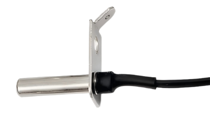
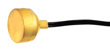
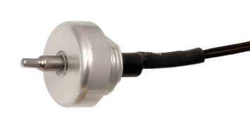
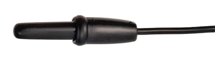
1.Product probe size specifications (tube,bullet,flange,etc.)
2.Product nominal resistance(resistance at R25℃or others)
3.B value coefficient(example:B3435,B3950,B4100,etc.)
4.Product accuracy requirements(1%~5%)
5.Wire type and length (UL2651,UL1332,UL3398,etc.)
6.End treatment (immersion tin,terminal,audio socket,cold-pressed terminal,etc.)
7.Operating temperature range8.Other requirements(casing,labeling,printing,independent packaging,cards,etc.)
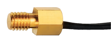
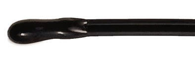
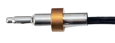
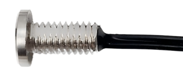
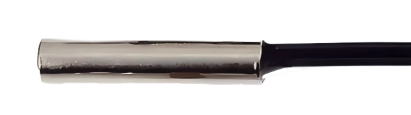
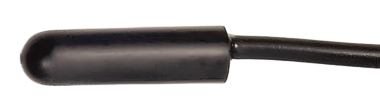
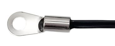
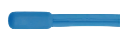
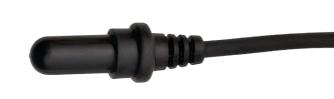
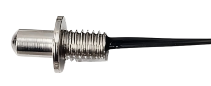
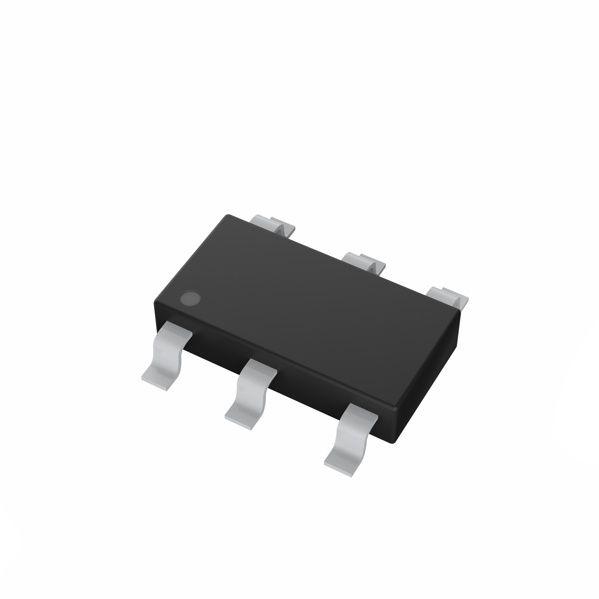
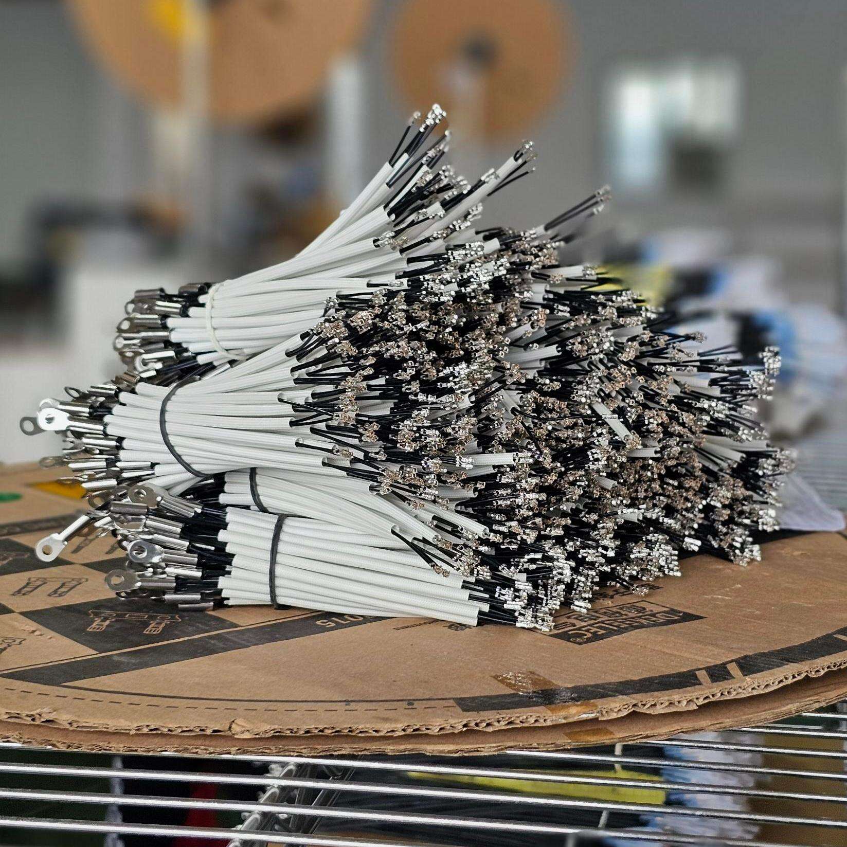
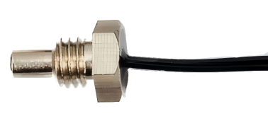
Product display
 |
|
|
|
|
|
|
|
|
|
|
|
|
|
|
|
|
|
|
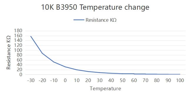
Change oftemperature resistance characteristic
| Temperature characteristic table | ||||||||||
| R25℃ | 5K | 5K | 10K | 10K | 10K | 47K | 50K | 50K | 68K | 100K |
| B25/50℃ | 3470 | 3950 | 3435 | 3470 | 3950 | 3950 | 3950 | 3977 | 3950 | 3950 |
| T(℃) | R(KQ) | R(KΩ) | R(KQ) | R(KΩ) | R(KQ) | R(KQ) | R(KΩ) | R(KΩ) | R(KQ) | R(KQ) |
| -30 | 52.1314 | 78.623 | 113.6351 | 107.3375 | 157.2459 | 739.4443 | 786.643 | 866.19 | 1168.57 | 1718.49 |
| -20 | 32.5659 | 43.7144 | 69.1948 | 67.0282 | 87.4288 | 432.7027 | 460.322 | 479.43 | 645.1514 | 948.752 |
| -10 | 21.0522 | 25.9077 | 43.3184 | 42.5511 | 51.8154 | 253.3925 | 269.567 | 276.61 | 372.7304 | 548.133 |
| 0 | 14.1005 | 15.885 | 27.766 | 27.4965 | 31.77 | 154.3095 | 164.159 | 162.96 | 221.0537 | 325.079 |
| 10 | 9.5512 | 9.841 | 18.0944 | 18.0967 | 19.6819 | 90.7864 | 96.581 | 99.473 | 135.8116 | 199.7229 |
| 20 | 6.484 | 6.2327 | 12.0956 | 12.131 | 12.4654 | 57.8945 | 61.59 | 62.449 | 85.124 | 125.1824 |
| 30 | 4.1496 | 4.0322 | 8.2746 | 8.2803 | 8.0644 | 38.4509 | 40.905 | 40.112 | 54.663 | 80.3868 |
| 40 | 2.8924 | 2.6636 | 5.781 | 5.7521 | 5.3271 | 25.9102 | 27.564 | 26.553 | 35.9929 | 52.9307 |
| 50 | 2.0321 | 1.796 | 4.1218 | 4.064 | 3.592 | 16.8636 | 17.94 | 17.88 | 24.2733 | 35.696 |
| 60 | 1.4734 | 1.2359 | 2.9926 | 2.9183 | 2.4718 | 11.7564 | 12.507 | 12.383 | 16.73 | 24.6029 |
| 70 | 1.0783 | 0.8677 | 2.2082 | 2.1282 | 1.7353 | 8.2634 | 8.791 | 8.7463 | 11.7541 | 17.2854 |
| 80 | 0.798 | 0.6213 | 1.6526 | 1.5749 | 1.2425 | 5.8985 | 6.275 | 6.2794 | 8.3953 | 12.346 |
| 90 | 0.614 | 0.4542 | 1.2553 | 1.1818 | 0.9083 | 4.2727 | 4.545 | 4.4788 | 6.0706 | 8.9273 |
| 100 | 0.4674 | 0.3372 | 0.9662 | 0.8985 | 0.6744 | 3.1396 | 3.34 | 3.2942 | 4.4541 | 6.5502 |