What Are Bridge Rectifiers and How Do They Work?
Definition and Basic Function of Bridge Rectifiers
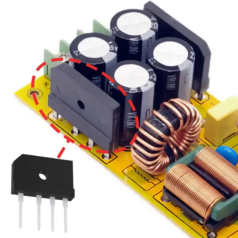
A bridge rectifier basically consists of four diodes arranged together to change alternating current into direct current through what's called full wave rectification. These differ from half wave versions because they actually make use of both sides of the AC signal instead of just one part, which cuts down on wasted energy and makes them about twice as efficient overall. The way these components are physically laid out in a bridge shape means there's no need for those special center tapped transformers that can get expensive. This saves money on parts for simple power supplies, maybe around 30 percent depending on design specifics. What matters most is that this setup keeps electricity flowing in one direction all the time, even when the input connection gets reversed accidentally.
The Role of Bridge Rectifiers in Modern Power Electronics
Bridge rectifiers play a key role in connecting AC power from wall outlets to all those DC devices we use daily, including our phones and smart home gadgets. These components form the starting point for most switched mode power supplies, helping convert electricity efficiently while keeping heat generation down. According to some recent market research from 2023, around 8 out of 10 small adapters below 100 watts actually contain bridge rectifiers because they strike a good balance between physical dimensions, manufacturing costs, and conversion rates typically ranging from 85% to just over 90%. What makes them so popular? Well, they don't need transformers, which means manufacturers can make smaller charging units without sacrificing too much performance. This is why our modern tech keeps getting tinier year after year.
Full-Wave Rectification Process: Simplified Explanation of AC to DC Conversion
The four-diode bridge operates in two phases:
- Positive half-cycle: Diodes D1 and D3 conduct, creating a forward current path
- Negative half-cycle: Diodes D2 and D4 activate, maintaining output polarity
This dual-path operation converts 60Hz AC input into 120Hz pulsating DC, which capacitors then smooth into stable voltage rails. Engineers favor this method over half-wave alternatives because it reduces ripple amplitude by 50% while doubling effective output voltage for the same transformer specifications.
Internal Circuit Design and Diode Operation in Bridge Rectifiers
Four-Diode Configuration and Component Layout in Bridge Rectifier Circuits
Bridge rectifiers use a four-diode arrangement to enable full-wave rectification without requiring a center-tapped transformer. In this configuration:
- Two diodes conduct during the AC input's positive half-cycle (typically D1 and D3)
- The remaining two activate during the negative half-cycle (D2 and D4)
This layout ensures current flows unidirectionally through the load regardless of AC polarity. Modern designs optimize spacing between components to minimize electromagnetic interference (EMI) and heat buildup, improving reliability in high-frequency applications.
Current Flow During Positive and Negative Half-Cycles of AC Input
When we look at what happens during the positive half cycle, the incoming voltage actually causes diodes D1 and D3 to conduct electricity. This creates a clear path for current flowing from the AC source's live terminal all the way through our load and back to neutral. Now when the negative half cycle comes along, things flip around completely. The polarity reversal activates diodes D2 and D4 instead. Even though the direction has changed, the current still flows through the load in exactly the same manner as before. What makes this whole setup so effective is that it essentially doubles up on the output frequency when compared with those basic half wave rectifiers out there. And because of this doubling effect, the amount of ripple in the signal gets reduced quite a bit even before any additional filtering takes place.
Voltage Drop Considerations: Silicon vs. Schottky Diodes
Regular silicon diodes typically create around 0.7 volts drop each one, so when used in a bridge configuration they can eat up to 1.4 volts altogether. This means output voltage drops somewhere between 5 to 10 percent in those low voltage systems we often deal with. Schottky diodes cut down on conduction losses by roughly 60 percent though, since they only drop about 0.3 volts per diode, totaling just 0.6 volts across the bridge. That's why many designers prefer these for battery powered gadgets where every milliamp counts. But there's a catch worth mentioning too. These Schottkys tend to leak more current, sometimes as much as 5 mA even at room temperature conditions. For this reason, engineers usually steer clear of them in precision analog work where controlling reverse currents matters most.
Smoothing Output: Filtering Ripple in DC Voltage
Understanding Pulsating DC and the Need for Ripple Reduction
Bridge rectifiers produce pulsating DC with residual ripple voltage, typically at 100 Hz in single-phase full-wave designs. This fluctuation can interfere with digital circuits and motor controllers. Ripple exceeding 5% of nominal voltage degrades component lifespan by 23% in switching power supplies (IEEE Power Electronics Society 2023), making filtering essential for sensitive electronics.
Capacitor Filtering: Role and Integration for Voltage Smoothing
Smoothing capacitors mitigate ripple through charge-discharge cycles:
- Store energy during AC waveform peaks
- Release stored current during voltage troughs
- Reduce ripple amplitude by 60–80%
Placed after the rectifier stage, electrolytic capacitors dominate due to high capacitance density (1–10,000 µF). Ceramic variants complement them in mixed architectures to suppress high-frequency noise.
Calculating Optimal Capacitance for Effective Ripple Suppression
Use this formula to determine minimum capacitance:
C = I_load / (f_ripple – V_ripple(max)) Where:
- I_load = Maximum load current (A)
- f_ripple = Ripple frequency (100 Hz for single-phase full-wave)
- V_ripple(max) = Acceptable peak-to-peak ripple voltage (V)
For a 2A load with 500 mV maximum ripple at 100 Hz:C = 2 / (100 – 0.5) = 40,000 µF
Oversizing by 20–30% compensates for capacitor aging and temperature effects.
Types of Bridge Rectifiers and Their Efficiency Advantages
Common Types: Standard Silicon, Schottky, SCR-Based, and Synchronous Rectifiers
Bridge rectifiers today come in four main types depending on what kind of efficiency matters most for different applications. The standard ones made from silicon diodes are still popular because they convert AC to DC at a reasonable price point. For situations where every volt counts, Schottky diode versions work better since they drop less voltage across their junctions. These are commonly seen in things like solar panel charge controllers where small differences matter a lot. Then there's SCR based models which give fine grain control over industrial motors, though nobody likes dealing with all the complicated trigger circuits needed to get them running properly. And finally we have these new synchronous rectifier designs using MOSFETs paired with intelligent controllers. They can slash conduction losses somewhere around 40 percent in those high frequency power supply setups, making them increasingly attractive despite higher initial costs.
Performance Comparison: Efficiency and Use Cases of Different Diode Technologies
A 2023 rectifier efficiency study revealed distinct tradeoffs:
| Technology | Efficiency Range | Ideal Use Case |
|---|---|---|
| Silicon Diode | 80–85% | Linear power supplies |
| Schottky | 88–92% | Low-voltage DC/DC converters |
| SCR-Based | 75–82% | Phase-controlled motor drives |
| Synchronous (MOSFET) | 94–97% | Server PSUs, EV chargers |
Schottky rectifiers dominate below 50V due to fast recovery times ( 10ns), while SCR variants excel in 100–500A industrial regulation.
High-Efficiency Applications Using MOSFET and Synchronous Rectifier Designs
The latest bridge rectifier technology has started incorporating Gallium Nitride MOSFETs, pushing telecom power system efficiencies close to 99%. This impressive figure comes from significantly reducing those pesky switching losses when operating above 1MHz frequencies. Looking at automotive applications, onboard chargers that employ synchronous topology designs cut down thermal stress by around 30% compared to old school diode stack approaches. We've seen this confirmed through extensive testing in electric vehicle systems recently. For wind turbines, engineers are experimenting with hybrid solutions that mix Silicon Carbide diodes with IGBT switches. These combinations show about 2% better peak efficiency in rectifier operations, all while managing demanding conditions of 3kV voltage and 100A current levels. Such improvements matter greatly in renewable energy contexts where every percentage point counts toward overall system performance.
Applications and Real-World Performance of Bridge Rectifiers
Key Applications in Power Supplies, Motor Drives, and Industrial Systems
Bridge rectifiers play a key role throughout today's electrical systems. These devices take alternating current and turn it into direct current with impressive efficiency, which is why they're so important for computer power supplies. Without them, those delicate circuit boards would get unstable voltage spikes that could damage everything from hard drives to motherboards. In industrial settings, manufacturers put bridge rectifiers to work controlling how fast motors spin and how much force they generate. We see them all over factories too, powering welders and running automated assembly lines. For places where power outages just aren't an option, like hospitals and server farms, uninterruptible power supplies depend on these components to switch between utility power and backup generators without missing a beat. That smooth transition keeps life-saving machines running and prevents data loss when the grid acts up.
Advantages Over Half-Wave and Center-Tapped Full-Wave Rectifiers
Bridge rectifiers stand out from half wave rectifiers which basically throw away half the AC signal, or those center tapped models that need special transformers. With bridge rectifiers we get full wave conversion using regular components found at any electronics store. No need for those tricky center taps anymore, so systems become simpler to build and about 30 percent cheaper for most power applications around town. Another big plus is how they cut down on peak inverse voltage stress by almost half when compared to setups with just two diodes. This means parts last longer in tough spots like electric vehicle charging stations where reliability matters a lot.
Measuring Efficiency and Reliability in Practical Power Conversion Scenarios
When evaluating performance, engineers look at how well a system suppresses ripples, usually aiming for less than 5% in good setups, along with checking thermal stability when things get loaded up. For MOSFET based designs that are supposed to be pretty efficient, load bank tests help confirm if they actually hit those 95% plus marks. Thermal imaging comes into play too, especially when dealing with components that switch at high frequencies since these tend to create hot spots that need attention. Industrial grade equipment typically lasts really long before needing replacement, with mean time between failures often going beyond 100 thousand hours. That kind of reliability makes sense why these units work so well in places where downtime is not an option like telecom infrastructure or solar farms where constant operation matters most.
FAQ
What is a bridge rectifier used for?
A bridge rectifier is used to convert alternating current (AC) into direct current (DC), commonly utilized in power supplies, motor drives, and electronic devices to ensure stable and efficient power conversion.
Why is a bridge rectifier more efficient than a half-wave rectifier?
A bridge rectifier is more efficient than a half-wave rectifier because it uses both halves of the AC cycle, reducing energy waste and doubling efficiency while eliminating the need for center-tapped transformers.
What are the advantages of using Schottky diodes in bridge rectifiers?
Schottky diodes in bridge rectifiers offer lower voltage drops, reducing power loss and improving efficiency, especially in low-voltage applications where every watt counts.
How does capacitor filtering work in bridge rectifier circuits?
Capacitor filtering in bridge rectifier circuits works by storing energy during AC waveform peaks and releasing it during voltage troughs, reducing ripple amplitude and ensuring smooth DC output.
What is the role of MOSFETs in modern bridge rectifier designs?
MOSFETs in modern bridge rectifier designs increase efficiency by reducing conduction losses and improving performance in high-frequency applications, beneficial for compact and energy-efficient electronic systems.
Table of Contents
- What Are Bridge Rectifiers and How Do They Work?
- Internal Circuit Design and Diode Operation in Bridge Rectifiers
- Smoothing Output: Filtering Ripple in DC Voltage
- Types of Bridge Rectifiers and Their Efficiency Advantages
- Applications and Real-World Performance of Bridge Rectifiers
- Key Applications in Power Supplies, Motor Drives, and Industrial Systems
- Advantages Over Half-Wave and Center-Tapped Full-Wave Rectifiers
- Measuring Efficiency and Reliability in Practical Power Conversion Scenarios
-
FAQ
- What is a bridge rectifier used for?
- Why is a bridge rectifier more efficient than a half-wave rectifier?
- What are the advantages of using Schottky diodes in bridge rectifiers?
- How does capacitor filtering work in bridge rectifier circuits?
- What is the role of MOSFETs in modern bridge rectifier designs?