How Bridge Rectifiers Enable Efficient AC to DC Conversion
The Role of Bridge Rectifiers in AC/DC Conversion Process
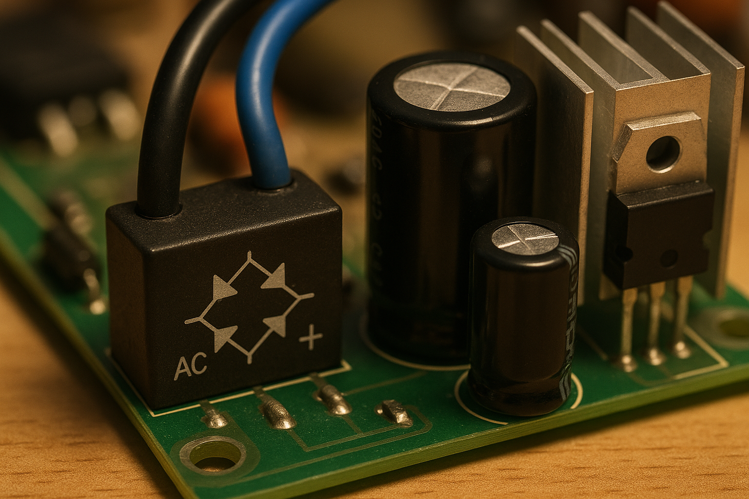
Bridge rectifiers play a key role in turning alternating current (AC) into direct current (DC), something almost all modern electronics need to function properly. Think about everyday gadgets like our phones or those charging stations for electric cars. Regular half wave rectifiers basically throw away half of what they receive from the AC source, but bridge rectifiers work differently. They employ four diodes arranged in a special way so they can capture both sides of the electrical wave, whether it's positive or negative. Because these components make good use of the entire signal, they typically operate at around 80% efficiency or better. This means less energy gets wasted as heat during conversion, which is why engineers often prefer them when designing power supplies that need to perform well under various conditions.
Full-Wave vs. Half-Wave Rectification: Performance and Efficiency
Full-wave rectification significantly outperforms half-wave designs in efficiency and output consistency. The table below highlights key differences:
| Parameter | Half-Wave Rectifier | Full-Wave Bridge Rectifier |
|---|---|---|
| Utilized Cycles | Only positive half-cycle | Entire AC waveform |
| Typical Efficiency | ~40% | >81% |
| Transformer Usage | Partial | Complete duty cycle |
By using the entire AC cycle, full-wave rectifiers deliver double the output power for the same input compared to half-wave versions. They also produce lower ripple voltage, reducing stress on components and improving system longevity.
Diode Conduction During Positive and Negative Half-Cycles
When the AC input goes positive, diodes D1 and D3 start conducting electricity and send it through the load in one particular direction. Then comes the negative half cycle where things switch around completely different diodes D2 and D4 now handle the job while keeping the same polarity at the output end. This back and forth switching prevents any reverse voltage from appearing across whatever device we're powering. According to some thermal tests done on these circuits, running current through two paths instead of just one cuts down heat loss by about 28 percent when compared to older designs with separate individual diodes. The result? Better efficiency overall plus cleaner DC power that still has those characteristic pulses but stays steady enough so filters can do their work properly later on.
Circuit Design and Operational Principles of Bridge Rectifiers
Four-Diode Bridge Configuration and Current Path Analysis
A bridge rectifier works because it has these four diodes arranged in a loop that basically lets it grab both halves of the AC wave. When the voltage goes up on the positive side, diodes D1 and D3 start conducting electricity. Then when things flip to negative, D2 and D4 take over instead. What this means for anyone working with electronics is pretty straightforward: regardless of which way the current is flowing through the circuit, it always ends up going through the load component in the same direction. This setup gets rid of those annoying gaps where nothing happens in regular half-wave rectifiers. The result? The whole AC signal gets converted into DC power that still pulses but doesn't waste any part of the original waveform, so we're getting maximum possible energy out of our system without losing efficiency somewhere along the line.
Operation Across Complete AC Input Cycles
When bridge rectifiers process all of the AC input, they actually double up on the ripple frequency. So what does this mean? Well, if we start with a standard 60 Hz supply, it creates a 120 Hz ripple effect instead. And for those working with 50 Hz systems, expect around 100 Hz ripple as a result. The benefit here is pretty straightforward - these higher frequencies make filtering much easier and help keep power delivery more stable across different loads. Another important aspect worth mentioning is how balanced current paths stop transformer cores from getting saturated. This becomes especially valuable when dealing with switched mode power supplies commonly used in modern electronics manufacturing or heavy duty industrial applications where reliability matters most.
Voltage Drop, Conduction Losses, and Real-World Diode Behavior
Silicon diodes typically create a forward voltage drop around 0.7 volts each time they conduct electricity, so when two are used together we see about 1.4 volts lost during each cycle according to the Semiconductor Industry Report from 2023. All these small losses add up and generate heat, especially when dealing with large amounts of current flowing through circuits. The relationship between power loss and current follows the basic formula P equals I squared R, which means higher currents lead to exponentially greater losses. For dealing with this issue, many engineers turn to Schottky diodes instead since they only drop about 0.3 volts, making them ideal for circuits operating at lower voltages. In situations where power levels get really high, additional measures become necessary such as adding metal heatsinks or even incorporating fans for active cooling solutions in industrial equipment.
| Parameter | Half-Wave Rectifier | Bridge Rectifier | Improvement |
|---|---|---|---|
| Conduction Period | 50% of cycle | 100% of cycle | 2× utilization |
| Ripple Frequency | 60 Hz | 120 Hz | 2× smoother output |
| Transformer Stress | High | Balanced | Reduced saturation risk |
Thermal management is crucial: a 15°C rise can reduce diode lifespan by 40% (Electronics Reliability Journal 2022). Modern designs address this with heatsinked arrays and current-sharing topologies.
Optimizing Output Quality: Ripple Reduction and Filtering Techniques
Using Capacitors and Inductors to Smooth DC Output
Bridge rectifiers need filtering components to turn that wobbly DC power into something stable enough for most circuits. Capacitors basically soak up those voltage spikes when they come along and then let out stored energy when things dip down. Inductors work differently but just as important they push back against sudden surges or drops in current flow. Some tests from around 2021 showed that good quality LC filters can cut down on those annoying ripples by somewhere between two thirds and four fifths compared to what happens with just basic setups. When dealing with really demanding equipment where stability matters a lot, engineers often go for choke input filters which mix both inductors and capacitors together. These combinations tend to smooth things out much better than either component alone could manage.
| Component | Primary Role | Impact on Ripple |
|---|---|---|
| Capacitor | Voltage stabilization | Reduces peak-to-peak variation by 40–60% |
| Inductor | Current filtering | Attenuates high-frequency noise by 30–50% |
Balancing Ripple Frequency, Component Size, and System Efficiency
Full wave rectifiers double the ripple frequency compared to their half wave counterparts, which means engineers can get away with about half the component size when designing filters. Most professionals rely on the basic ripple formula V_ripple equals I_load divided by twice the frequency times capacitance to find that sweet spot between capacitor size, ESR values, and what the system can handle thermally before things start getting hot. Ceramic capacitors these days are pretty impressive too, maintaining under 5% capacitance variation across temperatures ranging from minus 40 degrees Celsius all the way up to 125 degrees. This stability makes them ideal for creating small form factor designs that still work reliably in tough environments.
Efficiency Challenges: Thermal Management in High-Power Applications
In rectifiers above 500W, diode conduction losses account for 70–90% of waste heat. Each 10°C temperature rise increases forward voltage drop by 2–3%, risking thermal runaway. Effective mitigation strategies include:
- Aluminum heatsinks (≈3°C/W thermal resistance)
- Active cooling for loads exceeding 1 kW
- Snubber circuits to suppress switching transients
Proper thermal design improves overall system efficiency by 12–15% during continuous operation (recent studies).
Advantages of Full-Wave Bridge Rectifiers Over Half-Wave Designs
Superior Power Utilization and Output Voltage Consistency
Full-wave bridge rectifiers utilize both halves of the AC waveform, achieving near-total input utilization versus 50% in half-wave designs. This results in doubled ripple frequency (100–120 Hz), enabling simpler, smaller filters. The output voltage remains stable at approximately 0.637×Vpeak, minimizing sag under load.
| Feature | Full-Wave Rectifier | Half-Wave Rectifier |
|---|---|---|
| AC Utilization | 100% | 50% |
| Ripple Frequency | 2× Input Frequency | Equal to Input |
| DC Output Stability | High | Moderate |
Improved Transformer Utilization and System Reliability
Bridge rectifiers eliminate the need for center-tapped transformers, reducing cost and complexity. Symmetrical current flow prevents magnetic imbalance, a common cause of transformer failure in high-power half-wave systems. Thermally balanced operation extends diode lifespan by 25–40%, enhancing long-term reliability.
Real-World Applications of Bridge Rectifiers in Modern Power Systems
Power Supplies for Consumer and Industrial Electronics
Bridge rectifiers show up everywhere these days in AC adapters for things like laptops, smartphones, and all sorts of internet connected gadgets. They take the messy AC coming out of wall sockets and turn it into steady DC power that electronics actually need to work properly. When we look at industrial applications, these little components keep motors running smoothly and PLC systems operating correctly despite the constant electrical noise around factories. The full wave design really shines when compared to those old half wave versions. It cuts down on voltage fluctuations by about half at the same frequency, which means manufacturers can build smaller power supplies that still get the job done efficiently without wasting energy.
Front-End AC to DC Conversion in EV Charging Stations
At EV charging stations, bridge rectifiers perform initial AC-to-DC conversion before DC-DC modules adjust voltage for battery charging. Using silicon carbide diodes, modern units achieve over 98% efficiency during Level 2 charging, minimizing heat and enabling reliable 50kW+ power delivery without transformer saturation.
Integration in DC Fast Charging and Renewable Energy Systems
The latest generation of ultra fast 350kW electric vehicle chargers incorporates parallel bridge rectifier banks which help keep the 800V DC bus stable even when there are fluctuations in the power grid. When it comes to solar installations, micro inverters actually work with bridge rectifiers too. These components take the varying AC output from those photovoltaic panels and turn it into direct current for maximum power point tracking. According to field data from NREL in 2023, this approach cuts down on energy losses by about 12% compared to what we see with traditional methods. What makes these systems really interesting is their ability to scale up, something that becomes especially valuable when dealing with bidirectional power flows in both vehicle to grid scenarios and various renewable storage applications across different industries.
FAQ
What is the main advantage of bridge rectifiers over half-wave rectifiers?
Bridge rectifiers utilize both halves of the AC waveform, which results in higher efficiency and output power. They also provide more stable DC output, reducing stress on components and improving the system's longevity.
How do bridge rectifiers improve the efficiency of AC to DC conversion?
Bridge rectifiers capture both sides of the electrical wave and utilize the entire AC cycle, achieving around 80% efficiency or better. This minimizes energy waste and reduces heat loss during the conversion process.
Why is ripple frequency important in rectifiers?
Higher ripple frequency makes filtering easier and helps maintain stable power delivery across different loads. It also reduces the size of filtering components needed for smoothing ripple and enhances the overall efficiency of power systems.
What role do capacitors and inductors play in smoothing DC output?
Capacitors reduce voltage spikes and stabilize voltage variation, while inductors filter high-frequency noise and manage current surges. Together, they significantly minimize ripple and improve DC power quality.
Table of Contents
- How Bridge Rectifiers Enable Efficient AC to DC Conversion
- Circuit Design and Operational Principles of Bridge Rectifiers
- Optimizing Output Quality: Ripple Reduction and Filtering Techniques
- Advantages of Full-Wave Bridge Rectifiers Over Half-Wave Designs
- Real-World Applications of Bridge Rectifiers in Modern Power Systems
- FAQ