Discover how Metal Oxide Varistors (MOVs) provide effective EMI suppression and surge protection in brushed DC motor systems. Learn about their clamping characteristics, packaging options (SMD and DIP), selection guidelines, and comparison with TVS diodes for enhanced EMC performance in industrial applications.
1. Introduction
Brushed DC motors are widely used in compact machinery, power tools, toys, and automotive electronics due to their simple structure, low cost, and flexible control. Their operation is based on commutation via brushes and commutators, which enables continuous rotation through periodic current switching in the armature windings.
Despite challenges such as brush wear and electrical noise, brushed motors remain irreplaceable in certain applications due to their excellent speed control characteristics and proven structural reliability.
2. Electromagnetic Interference Issues and Protection Strategies
During operation, brushed motors generate arcs and transient voltage surges during brush commutation, resulting in:
High-energy surges that may damage sensitive circuit components.
Excessive EMI (Electromagnetic Interference) that may prevent compliance with EMC standards.
While BDL filters (low-pass filters composed of common-mode chokes and capacitors) are commonly used to suppress noise, they are sometimes insufficient in complex environments. Therefore, integrating Metal Oxide Varistors (MOVs) in parallel within the circuit is recommended as a reliable and efficient surge protection solution.
3. Operating Principle of MOVs
MOVs are clamping-type devices with nonlinear voltage-current characteristics, composed of sintered zinc oxide microcrystals and high-resistance insulating media.
Under normal voltage conditions, MOVs exhibit extremely high resistance and remain non-conductive. When the applied voltage exceeds the threshold, a low-resistance path is formed inside the device, rapidly conducting current and clamping the overvoltage to a safe level, thereby protecting downstream components from surge damage.
4. Comparison with TVS Diodes
TVS (Transient Voltage Suppression) diodes use semiconductor PN junctions and are ideal for high-frequency, high-speed data protection. In contrast, MOVs, being polycrystalline ceramic composites, offer higher energy absorption capacity and current handling capabilities, making them suitable for AC power lines and high-power equipment.
Additionally, due to their relatively large parasitic capacitance, MOVs can replace 2 to 5 discrete filter capacitors in some circuits, contributing to a more optimized overall design.
5. Key Parameters of MOVs
Vrms / Vw: Maximum continuous operating voltage without activation.
IL: Leakage current under the maximum operating voltage, typically ≤ 20 μA.
V1mA: Breakdown voltage measured at 1 mA current, close to the device’s activation threshold.
Vc: Maximum clamping voltage under a standard 8/20 μs surge waveform (8 μs rise time, 20 μs half-peak duration).
IPP: Peak surge current capability under specified test conditions (8/20 μs waveform, two pulses, 2-minute interval).
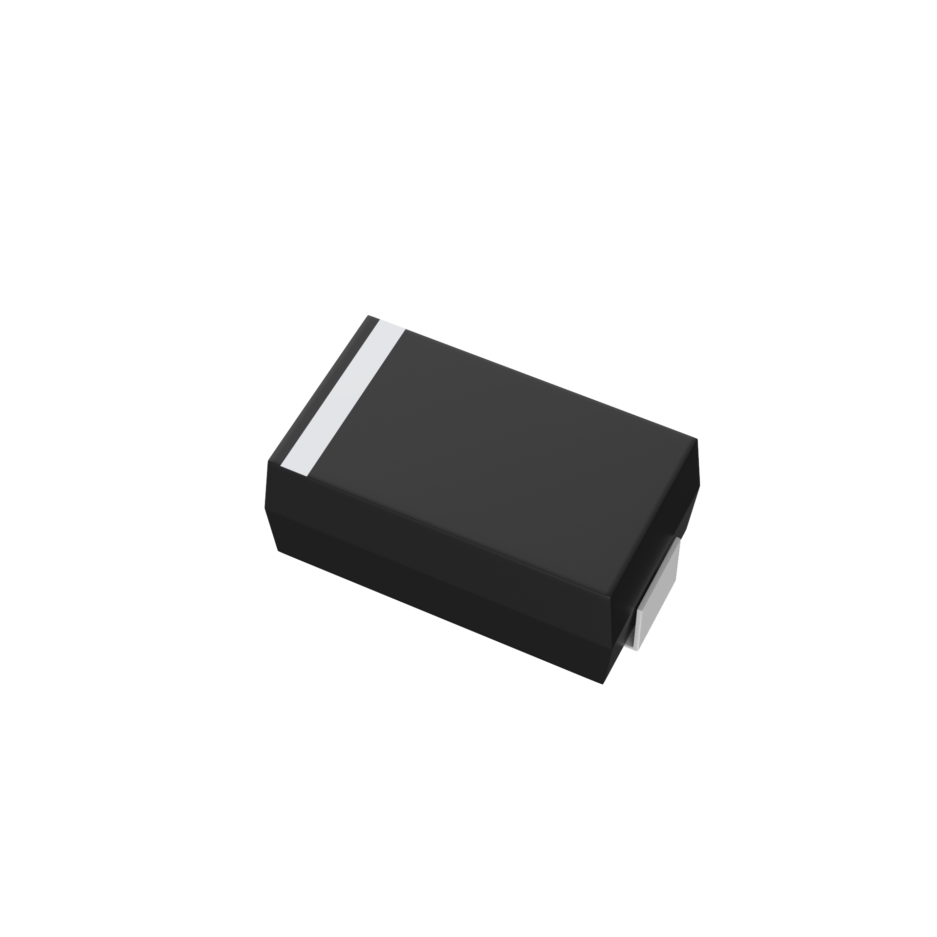
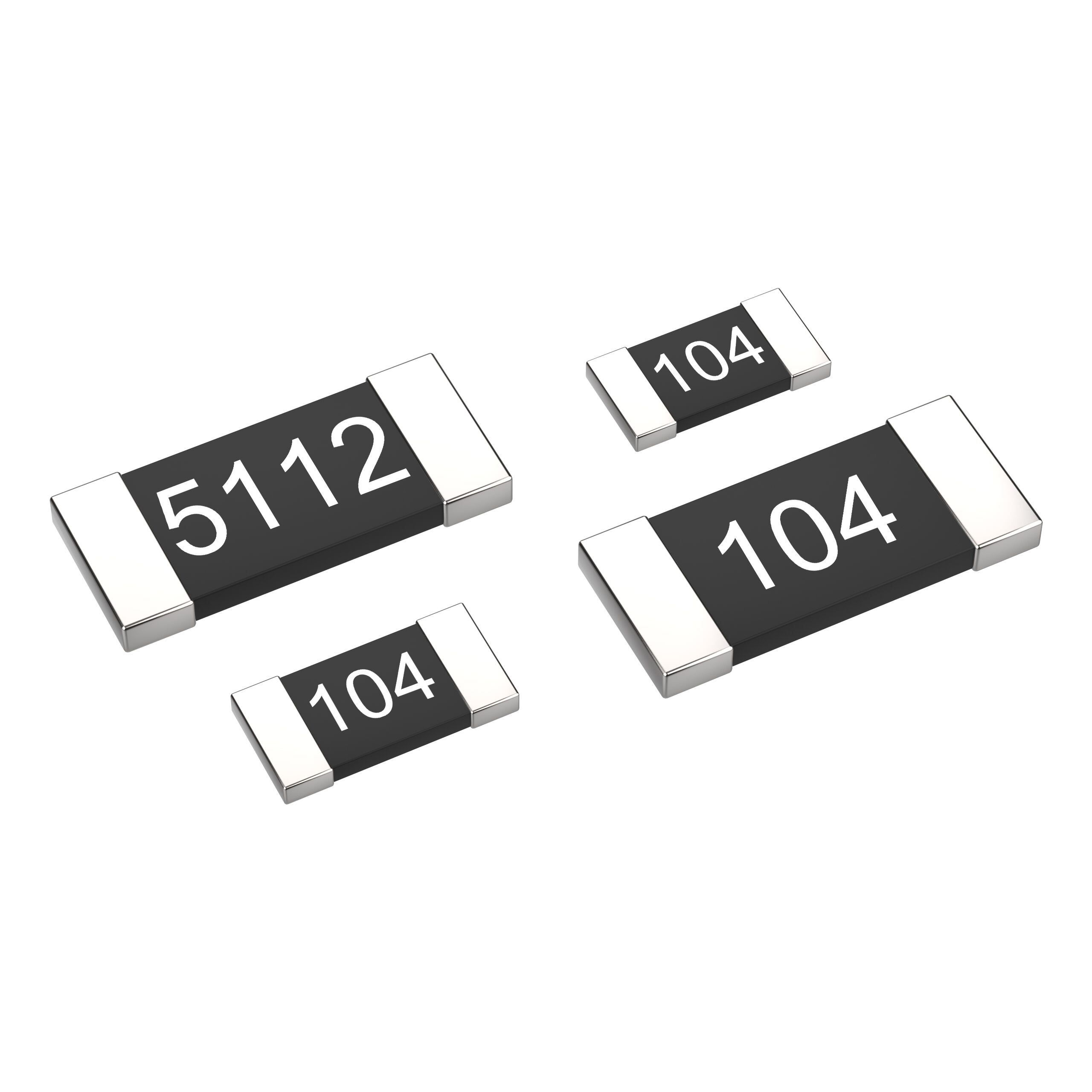
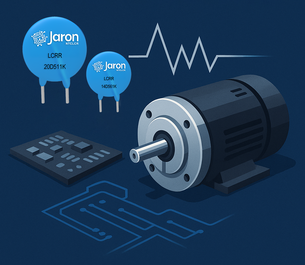
6. SMD Package Applications
For small brushed DC motors and compact electronic products, SMD-type MOVs are recommended. These components offer small size and easy installation, ideal for applications with short-duration, low-amplitude surge protection requirements.
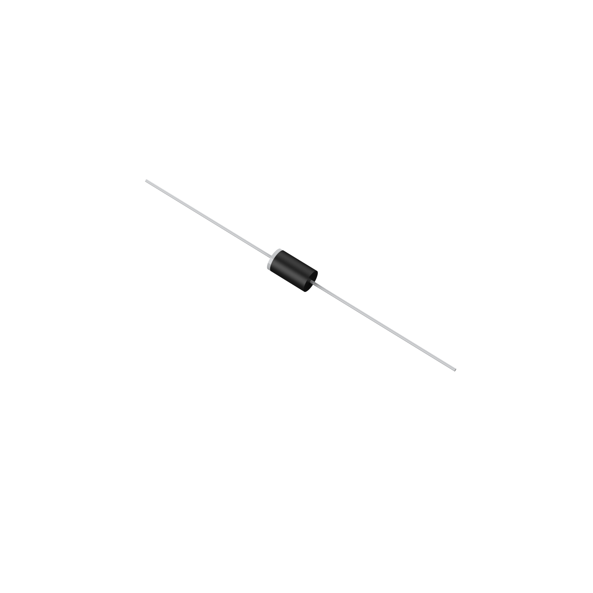
7. DIP Package Applications
For high-power motors and industrial drives, DIP (through-hole) MOVs are preferable. These devices have larger form factors and superior current handling, effectively managing high-energy surges and ensuring control circuit stability in harsh environments.
8. Selection Guidelines
MOV selection should consider motor operating voltage, allowable surge energy, and spatial constraints:
Low-power devices → SMD series MOVs
Medium to high-power systems → DIP type MOVs
Combining MOVs with BDL filters is also recommended to enhance overall EMI suppression performance.
9. Comparative Test Results
Without protection: Significant EMI noise and severe surge impacts observed.
With MOV + BDL solution: Surge voltages are effectively clamped, EMI levels reduced, and test results stable and compliant.
For precise analysis, oscilloscope waveforms before and after surge events, along with EMI spectrum measurements, are advised.
10. Advantages and Limitations of MOVs
Advantages:
Cost-effective
Mature technology and stable performance
High surge current capacity
Fast response time
Reduces need for additional filtering components
Limitations:
Relatively larger size, not ideal for highly integrated designs
High parasitic capacitance, unsuitable for high-speed signal lines
Usage Notes:
Operate within the specified temperature range
Avoid cleaning with strong polar solvents
Prevent mechanical stress or deformation
Fix components before bending leads, maintaining ≥ 2mm from the insulation layer
11. Conclusion
In complex EMC environments, selecting appropriate surge protection components tailored to specific application needs is essential for the long-term stability of motor control systems.
MOVs offer a cost-effective EMC solution for brushed motor systems due to their excellent current handling, affordability, and mature manufacturing process. We hope this analysis provides valuable insights and practical guidance for engineers in the field.